A blade and a rotary compressor with the blade

A rotor-type compressor technology, applied in mechanical equipment, machines/engines, liquid fuel engines, etc., can solve the problems of the decline of the mechanical efficiency of the rotor-type compressor, the reliability failure of the rotor-type compressor, and the insufficient lubrication. The effect of reducing friction loss, improving reliability, and improving performance

Active Publication Date: 2018-07-27
SHANGHAI HITACHI ELECTRICAL APPLIANCES CO LTD
View PDF7 Cites 0 Cited by
  • Summary
  • Abstract
  • Description
  • Claims
  • Application Information

AI Technical Summary

Problems solved by technology

[0003] During the working process of the rotor compressor, because the contact surfaces between the upper end surface and the lower end surface of the blade 9' and the upper cylinder cover 5 and the lower cylinder cover 6 are small, the lubricating oil is not easy to enter, so it is easy to cause insufficient lubrication and cause the rotor The mechanical efficiency of the rotary compressor decreases, and it may even lead to the failure of the reliability of the rotary compressor, causing failure

Method used


Image

  • A blade and a rotary compressor with the blade
  • A blade and a rotary compressor with the blade
  • A blade and a rotary compressor with the blade

Examples


no. 1 example

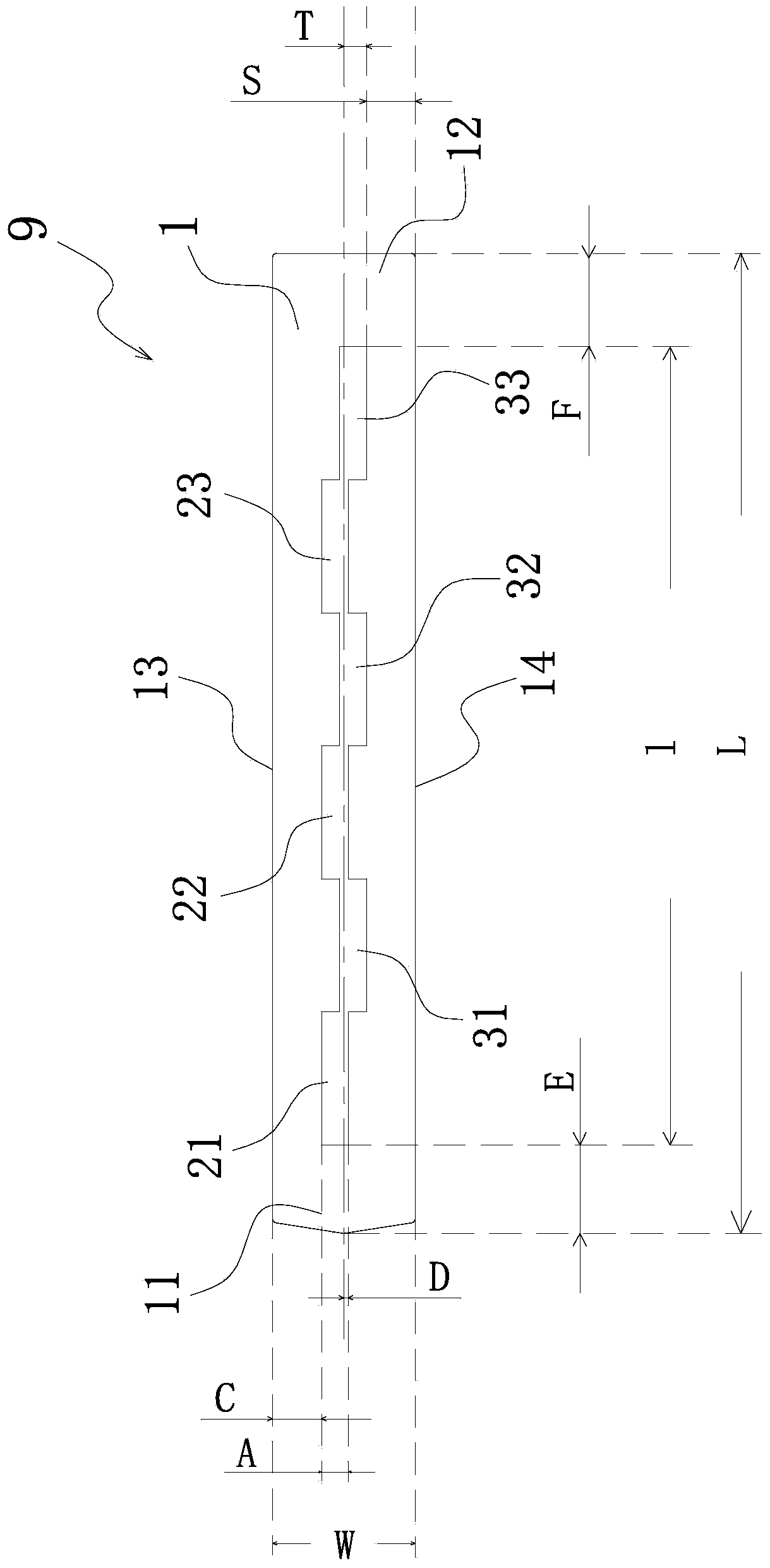
[0047] Please also see Figure 2 to Figure 4 , which respectively show a plan view, a front view and a longitudinal sectional view of the blade of the first embodiment of the present invention. exist Figure 2 to Figure 4 In the preferred embodiment shown, the blade 9 of the present invention includes: a blade body 1 and a groove-type oil storage mechanism. The groove type oil storage mechanism is arranged on the upper end surface and / or the lower end surface of the blade main body 1 . In the embodiment of the present invention, the groove type oil storage mechanism is only arranged on the upper end surface of the blade main body 1, and the figure 2 The upper end surface of the middle blade main body 1 will be described.

[0048] Such as figure 2 As shown, the blade body 1 includes a first end 11 and a second end 12 , and the direction from the first end 11 to the second end 12 is the length direction of the blade body 1 . The blade body also comprises a first side edge...

no. 2 example

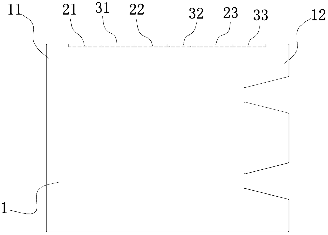
[0058] See Figure 6 , which shows a top view of a blade of a second embodiment of the present invention. with the above figure 2 The difference from the first embodiment shown in is that the adjacent first oil storage tank and the second oil storage tank are spaced apart from each other. Specifically, as Figure 6 As shown, the first oil storage tank 21 and the second oil storage tank 31 are spaced apart along the length direction of the blade main body 1, and the second oil storage tank 31 is spaced apart from the first oil storage tank 22. Similarly, the first oil storage tank 22, The second oil storage tank 32 , the first oil storage tank 23 and the second oil storage tank 33 are all spaced apart from each other. This embodiment can also be implemented and will not be repeated here.

no. 3 example

[0060] See Figure 7 , which shows a top view of a blade of a third embodiment of the present invention. with the above figure 2 The difference from the first embodiment shown in is that the shapes of the first oil storage tank and the second oil storage tank are parallelograms. Specifically, as Figure 7 As shown, the first oil storage tanks 21, 22, 23 and the second oil storage tanks 31, 32, 33 are all in communication with each other. Wherein, the oil storage tanks 21 , 22 , 23 and the second oil storage tanks 31 , 32 , 33 are all parallelograms. It should be noted that the parallelograms mentioned here refer to parallelograms other than rectangles. This embodiment can also be implemented and will not be repeated here.

[0061] other embodiments

[0062] combined with the above Figure 2 to Figure 7 In the illustrated embodiment, it can be understood that the shapes of the oil storage tanks 21 , 22 , 23 and the second oil storage tanks 31 , 32 , 33 can be varied. Fo...


PUM


Abstract

The invention provides a blade and a rotor type compressor provided with the same. The blade is used for the rotor type compressor and comprises: a blade main body and a groove-shaped oil storage mechanism, wherein the blade main body is provided with an upper end face and a lower end face; the groove-shaped oil storage mechanism is arranged on the upper end face and / or the lower end face of the blade main body; the groove-shaped oil storage mechanism is separated from an edge of the blade main body; and the groove-shaped oil storage mechanism is asymmetrical relative to the blade main body along the length direction. The blade provided by the invention can be used for effectively improving a lubricating performance between the blade and an upper cylinder cover and a lower cylinder cover; and the reliability of the compressor is improved and the performance of the compressor is improved.

Description

technical field [0001] The invention relates to the field of air conditioning, in particular to a blade for a rotor compressor and a rotor compressor with the blade. Background technique [0002] See figure 1 , which shows a longitudinal sectional view of a rotary compressor in the prior art. Such as figure 1 As shown, the rotary compressor includes: a cylinder 4, an upper cylinder cover 5, a lower cylinder cover 6, a crankshaft 7, a piston 8 and blades 9'. Wherein, the upper cylinder head 5 is arranged above the cylinder 4; the lower cylinder head 6 is arranged below the cylinder 4, and together with the cylinder 4 and the upper cylinder head 5 forms a compression space. The crankshaft 7 protrudes into the compression space. The piston 8 is arranged on the crankshaft 7 and located in the compression space, and the piston 8 rotates in the compression space as the crankshaft 7 rotates. The vanes 9' are arranged between the upper cylinder head 5 and the lower cylinder hea...

Claims


Application Information

Patent Timeline
Patent Type & Authority Patents(China)
IPC IPC(8): F04C29/02
Inventor 戴虎明陈剑洲
Owner SHANGHAI HITACHI ELECTRICAL APPLIANCES CO LTD
Why Eureka
Try Eureka