Impeller And Impeller With Axial Flow Fan
An impeller and blade technology, applied in the field of impellers and axial flow fans with it, can solve the problems of product reliability reduction, excessive stress, abnormal vibration, etc.
- Summary
- Abstract
- Description
- Claims
- Application Information
AI Technical Summary
Problems solved by technology
Method used
Image
Examples
Embodiment 1
[0026] Hereinafter, an embodiment will be described using the drawings.
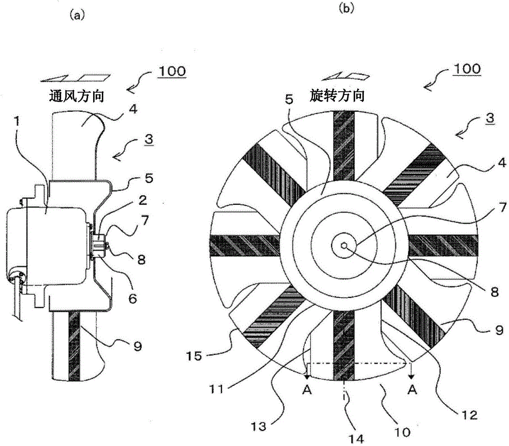
[0027] figure 1 It is a figure which shows the impeller of Example 1 and the axial flow fan which has it. figure 1 (a) A side view showing a partial section, figure 1 (b) shows a front view.
[0028] exist figure 1 Among them, 1 is the motor (motor), 2 is the rotating shaft, 3 is the impeller, 4 is the blade (blade), 5 is the hub (boss) part, 6 is the hub (hub) part, 7 is the washer (washer), 8 Is a bolt, and 9 is an aluminum plate.
[0029] The motor 1 is, for example, an induction motor driven at a variable speed by VVVF (Variable Voltage Variable Frequency) inverter power supply, and a propeller impeller 3 is attached to its rotating shaft 2 to constitute the main part of the axial fan 100 .
[0030] Although figure 1 Although not shown, the impeller 3 is covered by a case having a substantially cylindrical member called a pipe or a shroud, and the motor 1 is held by the case.
[0031] The impe...
Embodiment 2
[0055] Hereinafter, the impeller of Example 2 will be described. Embodiment 2 is different from Embodiment 1 in changing the shape of the aluminum plate, and the other basic structures of the impeller and axial flow fan are the same as Embodiment 1. The same applies to Examples 3 and 4.
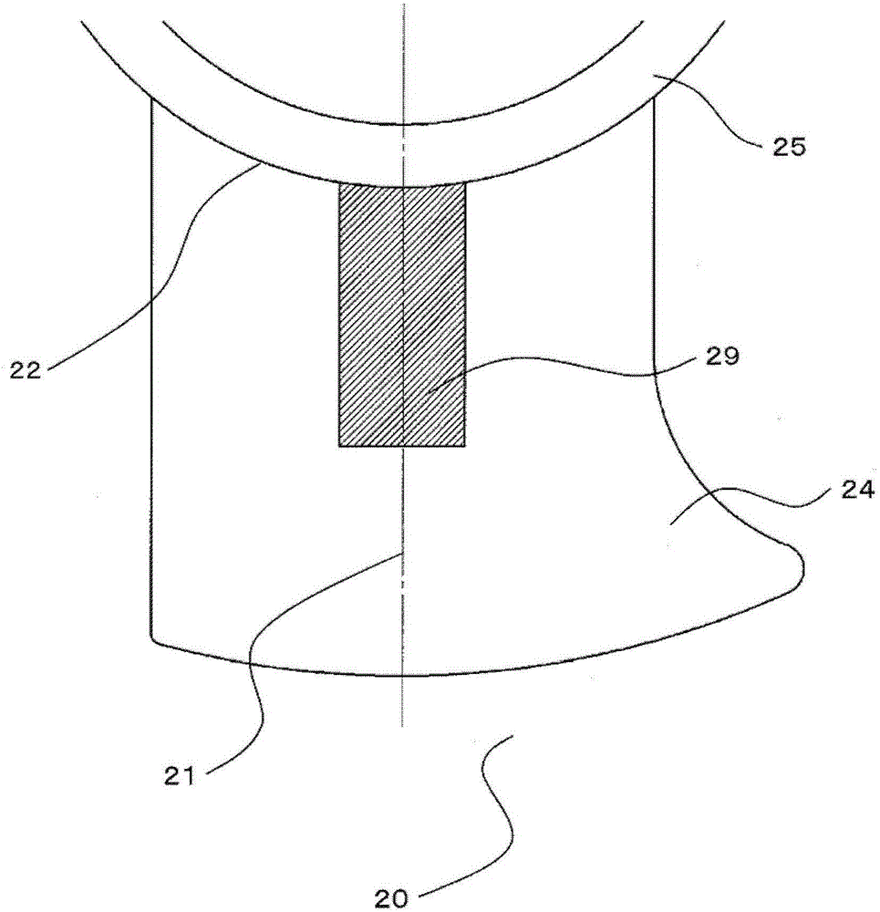
[0056] exist image 3 The structure of the junction body 20 of the blade 24 and the aluminum plate 29 provided in the impeller of Example 2 is shown. in addition, image 3 shows the structure of one joint body 20 among the plurality of joint bodies 20 (blades 24 ), Figure 4 , 5 It's the same.
[0057] The aluminum plate 29 of the second embodiment is formed narrower than the width of the blade 24, and extends a predetermined length in the radial direction of the blade 24 from the root 22 of the blade 24 (the boundary portion between the blade 24 and the hub member 25) along the centerline 21 of the blade 24. . That is, the aluminum plate 29 is installed so as not to reach the tip of t...
Embodiment 3
[0061] Next, the impeller of Example 3 will be described. exist Figure 4 The structure of the junction body 30 of the blade 34 and the aluminum plate 39 provided in the impeller of Example 3 is shown.
[0062] The aluminum plate 39 of Example 3 is formed to have approximately the same width as the width from the leading edge portion 31 to the trailing edge portion 32 of the blade 34 , and the width from the root portion 33 of the blade 34 (the boundary portion between the blade 34 and the hub member 35 ) is formed at the edge of the blade 34 . Extend radially to a specified length. That is, the aluminum plate 39 is installed so as not to reach the tip of the blade 34 .
[0063] By disposing the aluminum plate 39 from the root portion 33 of the blade 34 , it is possible to make the bonded body 30 less likely to be twisted. In addition, by forming the aluminum plate 39 to have substantially the same width as the width from the front edge portion 31 to the rear edge portion 3...
PUM
 Abstract
Description
Claims
Application Information
 - R&D
- Intellectual Property
- Life Sciences
- Materials
- Tech Scout
- Unparalleled Data Quality
- Higher Quality Content
- 60% Fewer Hallucinations
Browse by: Latest US Patents, China's latest patents, Technical Efficacy Thesaurus, Application Domain, Technology Topic, Popular Technical Reports.
© 2025 PatSnap. All rights reserved.Legal|Privacy policy|Modern Slavery Act Transparency Statement|Sitemap|About US| Contact US: help@patsnap.com


