Negative pressure type regulating valve for vacuumizing

A negative pressure, regulating valve technology, applied in the direction of valve lift, valve details, valve devices, etc., can solve the problems of pipe joints with single functionality, vacuum degree cannot be effectively controlled, and flow adjustment is not available, so as to increase the contact area , improved airtight performance, strong sealing and functional effects

Active Publication Date: 2017-03-08
海盐四通管件制造有限公司
View PDF5 Cites 9 Cited by
  • Summary
  • Abstract
  • Description
  • Claims
  • Application Information

AI Technical Summary

Problems solved by technology

[0007] The purpose of the present invention is to overcome the shortcomings of the above-mentioned prior art, and provide a negative pressure regulating valve for vacuuming, which aims to solve the problem that the functionality of the pipe joint in the prior art is relatively single, and it does not have the function of flow adjustment. During the vacuum process, the technical problem that the vacuum degree cannot be effectively controlled

Method used


Image

  • Negative pressure type regulating valve for vacuumizing
  • Negative pressure type regulating valve for vacuumizing

Examples


Embodiment Construction

[0023] In order to make the object, technical solution and advantages of the present invention clearer, the present invention will be further described in detail below with reference to the accompanying drawings and embodiments. However, it should be understood that the specific embodiments described here are only used to explain the present invention, and are not intended to limit the scope of the present invention. Also, in the following description, descriptions of well-known structures and techniques are omitted to avoid unnecessarily obscuring the concept of the present invention.

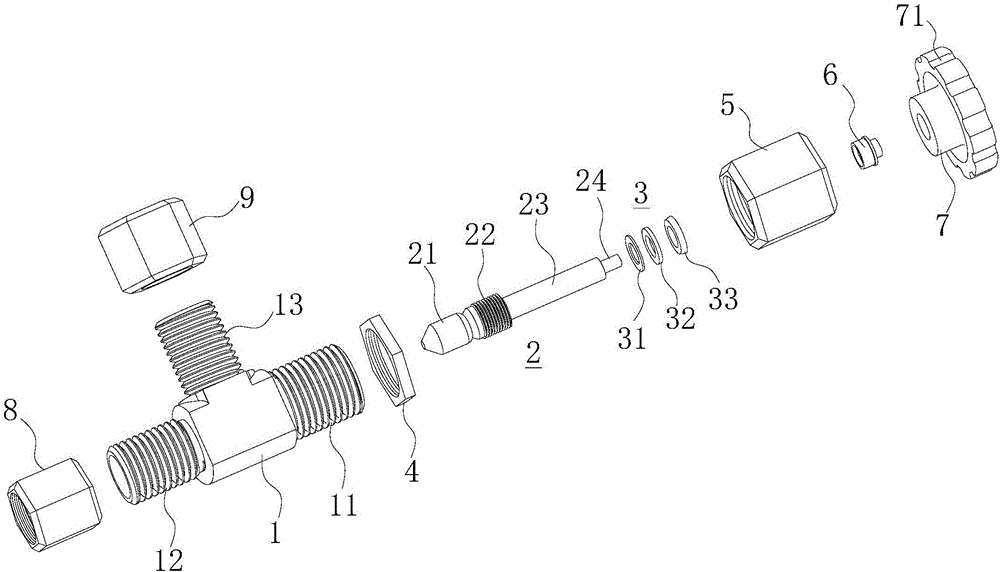
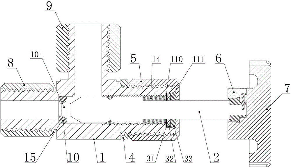
[0024] refer to figure 1 and figure 2 , the embodiment of the present invention provides a negative pressure regulating valve for vacuuming, including a valve body 1, a valve stem 2, a sealing assembly 3, a lock nut 4, a first nut 5, a positioning pressure sleeve 6, a rotating hand wheel 7, The second nut 8 and the third nut 9, the valve body 1 is a T-shaped three-way structure, and the thr...


PUM


Abstract

The invention discloses a negative pressure type regulating valve for vacuumizing. The negative pressure type regulating valve comprises a valve body, a valve rod, a seal assembly, a locknut, a first nut, a positioning pressing sleeve, a rotating hand wheel, a second nut and a third nut. The valve body is of a T-shaped three-way structure; a regulating internal thread is arranged in an inner cavity of a first joint of the valve body; the valve rod is of an integrated structure composed of a conical seal head and a long connecting rod; a regulating external thread is disposed at the tail end of the long connecting rod; the regulating external thread is in threaded connection with the regulating internal thread; a mounting groove is further formed in the valve body; a seal gasket is mounted in the mounting groove; the seal gasket is in conical surface seal connection with the conical seal head of the valve rod when the regulating valve is fully closed; the seal assembly is mounted at the outer end of the inner cavity of the first joint; the positioning pressing sleeve is connected with the tail end of the valve rod; and the rotating hand wheel is fixedly arranged on the positioning pressing sleeve in a sleeving mode. The negative pressure type regulating valve for vacuumizing is high in sealing performance, high in functionality and capable of effectively controlling the vacuum degree and improving vacuumizing effect.

Description

[0001] 【Technical field】 [0002] The invention relates to the technical field of valves, in particular to a negative pressure regulating valve for vacuuming. [0003] 【Background technique】 [0004] A pipe joint is a connecting part between one pipeline and another pipeline, and is a general term for a connection that can be assembled and disassembled in a fluid or gas passage. The current pipe joints only play the role of connection, and the adjustment of the flow rate requires other components to achieve, the functionality is relatively simple, and other components need to be added during installation to achieve the functions of connection and flow adjustment. [0005] In order to solve the above problems, enhance the functionality of the pipe joint, so that it not only has the function of connecting the pipeline, but also has the function of regulating the flow rate. The manifold joint and the flow regulating valve are integrated, which can realize simple installation. Duri...

Claims


Application Information

Patent Timeline
Patent Type & Authority Applications(China)
IPC IPC(8): F16K1/02F16K1/38F16K27/02F16K41/06
CPCF16K1/02F16K1/38F16K27/0254F16K41/06
Inventor 许明良
Owner 海盐四通管件制造有限公司
Why Eureka
Try Eureka