
A Multipoint Displacement Meter for Automatically Measuring Spatial Displacement

A technology of spatial displacement and displacement meter, applied in the direction of measuring devices, instruments, electrical devices, etc., can solve problems such as affecting the normal progress of scientific research work, large error in results, winding of wire ropes, etc., to achieve scientific spatial displacement laws, simple structure, The effect of improving work efficiency

Active Publication Date: 2018-10-23
SHANDONG UNIV OF SCI & TECH
View PDF4 Cites 0 Cited by
  • Summary
  • Abstract
  • Description
  • Claims
  • Application Information

AI Technical Summary

Problems solved by technology

[0002] Most of the multi-point displacement gauges currently used in coal mines are based on measuring the length of steel wire ropes. By calculating the length difference between two steel wire ropes, the separation of each rock layer inside the surrounding rock is estimated. This kind of multi-point displacement gauge is A relatively primitive test tool, which can only roughly measure the layer separation of surrounding rocks, and provide data support for the study of deep surrounding rock displacement laws
[0003] However, during the installation process of this multi-point displacement meter, the wire rope is prone to a series of problems such as winding, bending, and breaking, and the result obtained has a large error, and the result is only the change in the length of the wire rope after the spatial displacement of the rock formation. However, it cannot objectively and truly reflect the real situation of the spatial displacement of the rock formation; at the same time, when installing each pole of the multi-point displacement meter, it is necessary to send it to the interior of the surrounding rock with the help of a drill pipe, which is time-consuming and labor-intensive, and delays other production. The continuation of work has seriously affected the normal progress of scientific research work

Method used


Image

  • A Multipoint Displacement Meter for Automatically Measuring Spatial Displacement
  • A Multipoint Displacement Meter for Automatically Measuring Spatial Displacement
  • A Multipoint Displacement Meter for Automatically Measuring Spatial Displacement

Examples


Embodiment Construction

[0024] The technical solutions in the embodiments of the present invention will be clearly and completely described below with reference to the accompanying drawings in the embodiments of the present invention. Obviously, the described embodiments are only a part of the embodiments of the present invention, but not all of the embodiments. Based on the embodiments of the present invention, all other embodiments obtained by those of ordinary skill in the art without creative efforts shall fall within the protection scope of the present invention.

[0025] The purpose of the present invention is to provide a multi-point displacement meter for automatically measuring the spatial displacement, so as to solve the above-mentioned problems in the prior art, and can accurately measure the spatial displacement of each rock layer inside the surrounding rock of the roadway.

[0026] The invention provides a multi-point displacement meter for automatically measuring spatial displacement, co...


PUM


Abstract

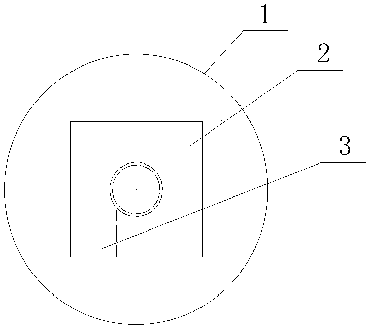
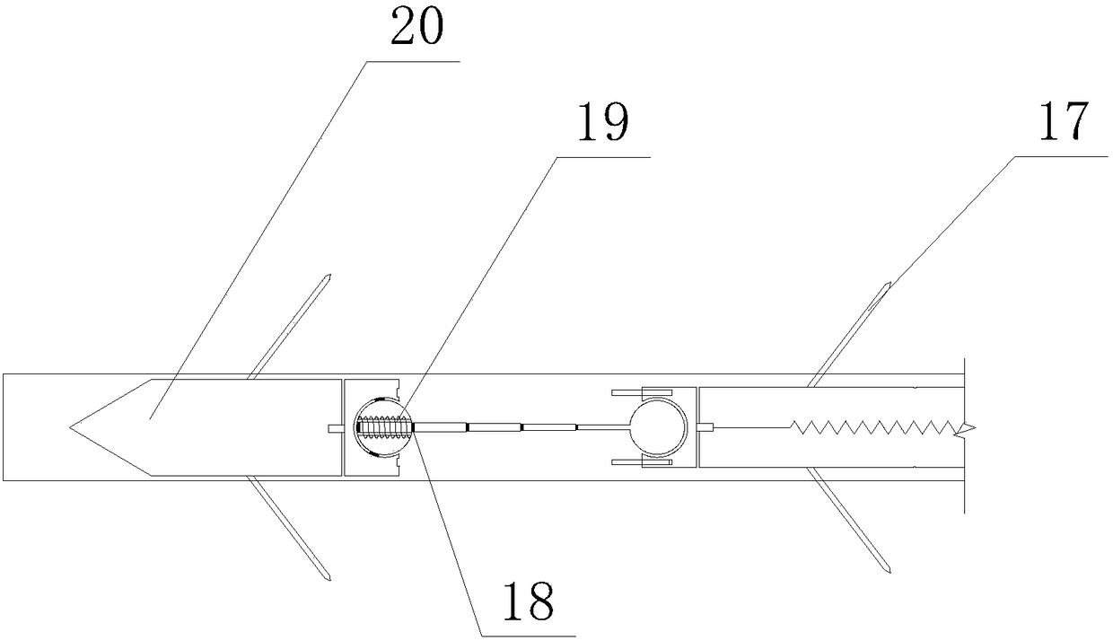
The invention provides a multi-point displacement meter for automatically measuring spatial displacement, including an explosion-proof online monitoring terminal, an explosion-proof bluetooth transmitter, a spatial displacement sensor, a wire, a drill pipe, a fixed pawl, and an end drill pipe. Adjust the length of each drill pipe according to the required measurement of rock layer separation, offset position and drilling depth, and then insert all the drill pipe parts into the drill hole, and the reference plate is close to the surrounding rock. When each rock layer is separated or offset, the rotating ball in the spatial displacement sensor rotates and the displacement telescopic rod extends. After that, the spatial displacement sensor will transmit the signal to the explosion-proof online monitoring terminal to process and store the data. When collecting data, the data is transmitted to the collector through the explosion-proof bluetooth transmitter. The invention combines the spatial displacement sensor, the drill pipe, the explosion-proof online monitoring terminal and the bluetooth device, and can accurately and scientifically study the movement law of the surrounding rock of the roadway in space, with real measurement and convenient installation.

Description

technical field [0001] The invention relates to the technical field of multi-point displacement meters, in particular to a multi-point displacement meter for automatically measuring spatial displacement. Background technique [0002] Most of the multi-point displacement meters currently used in coal mines are based on measuring the length of steel wire ropes. By calculating the length difference between two wire ropes, the separation of each rock layer inside the surrounding rock can be estimated. This multi-point displacement meter is a It is a relatively primitive test tool, which can only roughly measure the separation of the surrounding rock, and provides data support for the study of the displacement law of the deep surrounding rock. [0003] However, during the installation process of this multi-point displacement meter, the wire rope is prone to a series of problems such as winding, bending and breaking, and the obtained result has a large error, and the result is onl...

Claims


Application Information

Patent Timeline
Patent Type & Authority Patents(China)
IPC IPC(8): G01B7/02
CPCG01B7/02
Inventor 臧传伟谢帅李朋吴朋朋
Owner SHANDONG UNIV OF SCI & TECH
Learn More