Biometric identification device

A biometric, feature point technology, applied in character and pattern recognition, sensors, diagnosis, etc., can solve problems such as high power consumption, carrying and power supply limitations, and large volume.

Inactive Publication Date: 2017-03-08
EGALAX EMPIA TECH INC
View PDF9 Cites 6 Cited by
  • Summary
  • Abstract
  • Description
  • Claims
  • Application Information

AI Technical Summary

Problems solved by technology

It uses one or more light sources of visible light or invisible light to penetrate the finger skin tissue and blood or form reflections. When the heart contracts and relaxes, the blood flow in the blood vessels will cause subtle light changes, which are then detected by the photodetector. (photo detector) reception, from which you can know whether the heart is beating, the frequency or the subtler change signal, such as the monitoring equipment that is usually clamped on the finger or set on the finger in the hospital, but it has a large size and consumes a lot of power. problem, so it is limited in terms of portability and power supply
[0004] Since the use of portable electronic devices is very common nowadays, the problem of anti-theft has not been completely solved. Nowadays, fingerprint recognition technology can be seen on mobile phones. However, the current fingerprint recognition is still easy to be cracked. As people become more and more accustomed to using portable electronic devices, more and more private or confidential information is stored in them, so the function of anti-theft unlocking has attracted more and more attention from users. Therefore, the above-mentioned commonly used biometric features The identification device has many problems and deficiencies, so providing a biometric identification device that is small in size, easy to use and difficult to crack is the goal that the inventor and the R&D personnel engaged in this industry want to improve.

Method used


Image

  • Biometric identification device
  • Biometric identification device
  • Biometric identification device

Examples


Embodiment Construction

[0036] In order to achieve the above-mentioned purpose and effect, the technical means and structure adopted by the present invention are now illustrated in detail with respect to preferred embodiments of the present invention. Its features and functions are as follows, so as to fully understand the present invention.

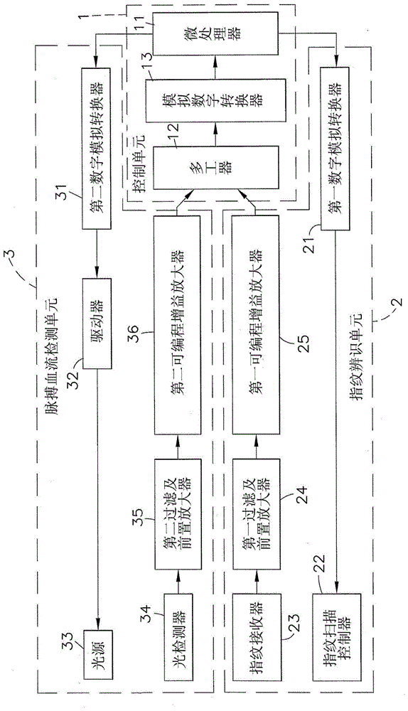
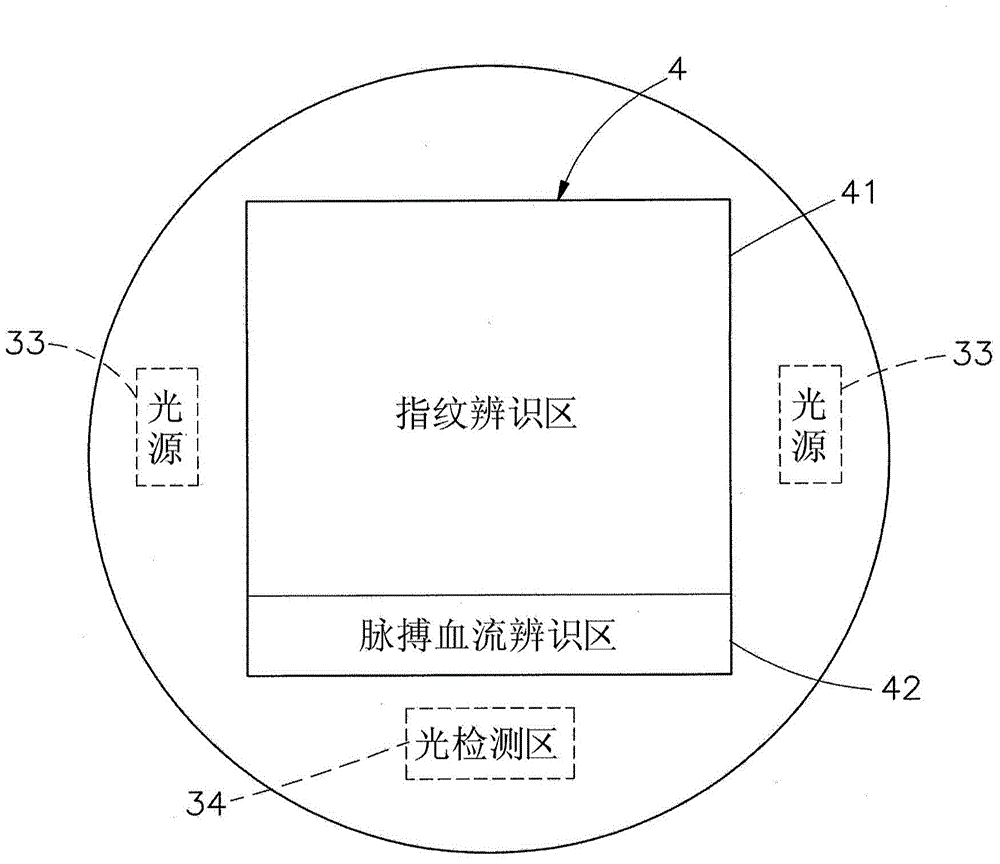
[0037] see figure 1 and figure 2 As shown, it can be clearly seen from the figure that the biometric identification device of the present invention mainly includes a control unit 1 , a fingerprint identification unit 2 , a pulse blood flow detection unit 3 and a base 4 .

[0038] The control unit 1 has a microprocessor 11, a multiplexer 12, and an analog-to-digital converter 13. An analog-to-digital converter 13 is electrically connected between the microprocessor 11 and the multiplexer 12, and the multiplexer 12 receives the fingerprint identification unit. 2 and the signal of the pulse blood flow detection unit 3 is transmitted to the analog-to-digital conv...


PUM


Abstract

The invention relates to a biometric identification device which comprises a control unit, a fingerprint identification unit which is electrically connected to the control unit, a pulse blood detection unit, and a seat body. The fingerprint identification unit has a fingerprint scanning controller and a fingerprint receiver, the pulse blood detection unit has at least one light source and a light detector. The top surface of the seat body has adjacent fingerprint identification area and pulse blood identification area, the area of the two areas is roughly equal to a single-finger pressing range, thus a user presses the fingerprint identification area and the pulse blood identification area with one finger in one time to detect fingerprint and pulse blood signals of the user, characteristic points are converted and extracted, the subsequent use is allowed when both the fingerprint and pulse blood signals are corrected, since the detection can be carried out with one time of one finger pressing, the device is convenient and fast to use, the difficulty of cracking is increased, and the anti-theft effect is better.

Description

technical field [0001] The present invention relates to a biometric identification device, in particular to a biometric identification device using two biometric identification technologies, including identifying fingerprints and sampling pulse blood flow signals, which can have better anti-theft when applied to unlocking devices Effect. Background technique [0002] As the problem of anti-theft unlocking is getting more and more attention in the market, traditional locks or combination locks, or unlocking devices applied to mobile phones are easy to be cracked, so manufacturers are researching and developing different anti-theft technologies. At that time, the gradually mature biometric identification technology has attracted the attention of manufacturers and consumers. The common biometric identification technology is to use detection components to identify fingerprints (Finger print), palm prints, face shapes, heartbeats, iris or DNA and other biological characteristics ...

Claims


Application Information

Patent Timeline
Patent Type & Authority Applications(China)
IPC IPC(8): G06K9/00A61B5/1172A61B5/1171
CPCA61B5/117G06V40/13G06V40/1306G06V40/1365
Inventor 林柏全
Owner EGALAX EMPIA TECH INC
Why Eureka
Try Eureka