Novel current transformer wiring terminal

A technology of current transformers and terminals, applied in the direction of inductors, transformers/inductor coils/windings/connections, circuits, etc., can solve the problems of inconvenient wiring of current transformers, and achieve a wide range of applications, ease of use, and safety factor. high effect

Inactive Publication Date: 2017-03-08
YANTAI POWER SUPPLY COMPANY OF STATE GRID SHANDONG ELECTRIC POWER +1
View PDF5 Cites 1 Cited by
  • Summary
  • Abstract
  • Description
  • Claims
  • Application Information

AI Technical Summary

Problems solved by technology

[0011] Compared with the prior art, the present invention can produce the following positive effects: the present invention can promptly and effectively solve the inconvenient wiring problem of the original current transformer, and is especially beneficial to the connection of multiple wires

Method used


Image

  • Novel current transformer wiring terminal
  • Novel current transformer wiring terminal
  • Novel current transformer wiring terminal

Examples


Embodiment

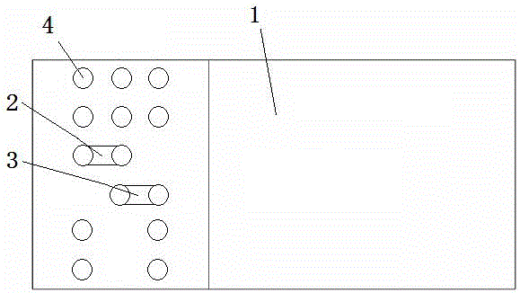
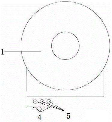
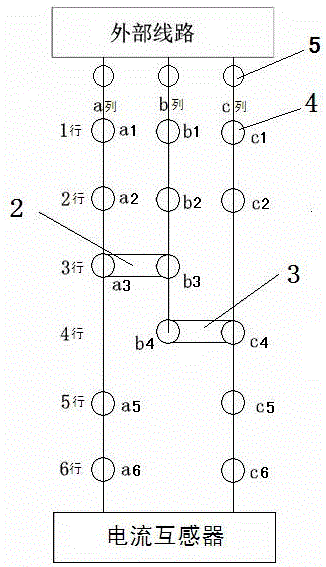
[0022] Embodiment: a new type of current transformer terminal (see Figure 1-Figure 3 ), which includes a current transformer 1. The terminal surface of the current transformer 1 is provided with a total of 14 crimping holes 4 in three columns and six rows. Among them, column a has three crimping holes in rows 1-3 and two in rows 5-6. 5 crimping hole a1, crimping hole a2, crimping hole a3, crimping hole a5, crimping hole a6 are composed of 5 interconnected crimping holes, column b crimping hole consists of 1-4 rows of four crimping holes that are connected to each other Hole b1, crimping hole b2, crimping hole b3, crimping hole b4, c crimping hole consists of two crimping holes in 1-2 rows, 3 crimping holes in 4-6 rows, a total of 5 crimping holes c1, crimping holes c1, crimping holes It consists of wire hole c2, wire hole c4, wire hole c5, and wire hole c6, wherein wire hole a3 and wire hole b3 are connected through the first connecting sheet 2, and wire hole b4 and wire hole...


PUM


Abstract

The invention discloses a novel current transformer wiring terminal. The novel current transformer wiring terminal comprises a current transformer (1) and is characterized in that a wiring end face of the current transformer (1) is provided with three columns and six rows of 14 pressure holes (4) with screws; the pressure holes in a column a are five communicated pressure holes including three pressure holes in first to third rows and two pressure holes in the fifth and sixth rows; the pressure holes in a column b include four communicated pressure holes in first to fourth rows; the pressure holes in a column c are five communicated pressure holes including two pressure holes in first and second rows and three pressure holes in fourth to sixth rows; a pressure hole a3 and a pressure hole b3 are connected through a first connection plate (2), and a pressure hole b4 and a pressure hole c4 are connected through a second connection plate (3); the lateral side of the wiring end of the current transformer (1) is provided with three wire insertion holes (5), and the three wire insertion holes (5) are communicated with the three columns of the pressure holes through conductors respectively; the pressure holes in each column are upwardly connected with an external circuit by the aid of wires through the three wire insertion holes (5) respectively and downwardly connected with the current transformer. The novel current transformer wiring terminal has advantages of simple principle, easiness in use, high operation efficiency, wide application range and high safety factor.

Description

[0001] Technical field: [0002] The invention relates to a novel transformer terminal, which is widely used in the field of high-voltage equipment in the electric power industry, and belongs to the technical field of electric power measurement. [0003] Background technique: [0004] The current transformer (Current Transformer, referred to as CT), its principle is based on the principle of electromagnetic induction, and consists of a closed iron core and a winding. Its primary winding has very few turns, and it is connected in series in the line of the current to be measured, so it often has all the current of the line flowing, and the secondary winding has a large number of turns, connected in series in the measuring instrument and the protection circuit, and the current mutual inductance When the transformer is working, its secondary circuit is always closed, so the impedance of the series coil of the measuring instrument and the protection circuit is very small, and the wo...

Claims


Application Information

Patent Timeline
Patent Type & Authority Applications(China)
IPC IPC(8): H01F27/29H01F38/30
CPCH01F27/29H01F38/30
Inventor 廖烽然陈泉曹勇宋春辉于林卉吕冬晓王炫丹于洨宋书强马传波
Owner YANTAI POWER SUPPLY COMPANY OF STATE GRID SHANDONG ELECTRIC POWER
Why Eureka
Try Eureka