Motor starting device

A technology for motor starting and installation slots, which is applied in the direction of circuit devices, emergency protection circuit devices, and power devices inside switches, etc. It can solve problems such as reduced work reliability, prolonged circuit cut-off time, and insufficient space, so as to save installation space, Optimize the effect of wire connection and structure setting ingeniously

Inactive Publication Date: 2017-03-08
HENGYANG RITAR POWER CO LTD
View PDF3 Cites 2 Cited by
  • Summary
  • Abstract
  • Description
  • Claims
  • Application Information

AI Technical Summary

Problems solved by technology

[0002] In the prior art, the motor starting device uses a static iron core and a moving iron core to directly drive the closing and opening of the contacts. The closing and opening are not fast enough to respond to the large inrush current in time, and it is easy to cause damage to the line. It is easy to burn under the impact of the impact current; the static iron core and the moving iron core used in the existing motor starting device are E-shaped or U-shaped, occupying a large space of the starter, and the space utilization is unreasonable. In addition, the E-shaped or U-shaped static iron core A spiral coil is wound on top to achieve the purpose of on-off contacts. Due to the performance limitations of the wire itself and the space limitation of the starter, the cross-sectional area of ​​the wire is limited within a certain range and cannot be too la

Method used


Image

  • Motor starting device
  • Motor starting device
  • Motor starting device

Examples


Embodiment Construction

[0023] The following will clearly and completely describe the technical solutions in the embodiments of the present invention with reference to the accompanying drawings in the embodiments of the present invention. Obviously, the described embodiments are only some, not all, embodiments of the present invention. Based on the embodiments of the present invention, all other embodiments obtained by persons of ordinary skill in the art without making creative efforts belong to the protection scope of the present invention.

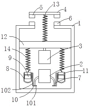
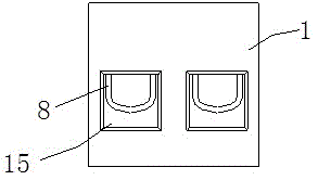
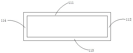
[0024] like Figure 1~4 As shown, a motor starting device includes an arc extinguishing cover 1, a static iron core 2 and a moving iron core 3 arranged in the arc extinguishing cover 1, and a contact plate 4 arranged above the arc extinguishing cover 1. The static iron core 2 and the moving iron core 3 are arranged oppositely, the bottom ends of the contact plate 4 are provided with moving contacts 5 respectively, and the top of the arc extinguishing cover 1 i...


PUM


Abstract

The invention discloses a motor starting device which comprises an arc extinguishing cover, a static core and a moving core arranged in the arc extinguishing cover, and a contact plate arranged above the arc extinguishing cover. Two ends of the bottom of the contact plate are provided with moving contact points. The top of the arc extinguishing cover is provided with static contacts which are corresponding to the moving contact points one to one. The static cores are in the shape of a hollow cylinder. An insulation sheath goes through the center of the static core and is internally provided with multiple parallel conductive wires. A conductive wire at the same side of the static core goes through the insulation sheath and then is split into two wire harnesses. Two sides of the static core are provided with two mounting grooves which are internally provided with wire connection bodies. The wire harnesses are connected to the wire connection bodies through a metal connection plate. The motor starting device provided by the invention has reasonable space utilization and can adapt to large impact current.

Description

technical field [0001] The present invention relates to the technical field of motors, and more specifically relates to a motor starting device. Background technique [0002] In the prior art, the motor starting device uses a static iron core and a moving iron core to directly drive the closing and opening of the contacts. The closing and opening are not fast enough to respond to the large inrush current in time, and it is easy to cause damage to the line. It is easy to burn under the impact of the impact current; the static iron core and the moving iron core used in the existing motor starting device are E-shaped or U-shaped, occupying a large space of the starter, and the space utilization is unreasonable. In addition, the E-shaped or U-shaped static iron core A spiral coil is wound on top to achieve the purpose of on-off contacts. Due to the performance limitations of the wire itself and the space limitation of the starter, the cross-sectional area of ​​the wire is limite...

Claims


Application Information

Patent Timeline
IPC IPC(8): H01H3/28H01H9/30H01H9/00H02H9/08
CPCH01H3/28H01H9/00H01H9/30H02H9/08
Inventor 熊鲜明夏朝阳
Owner HENGYANG RITAR POWER CO LTD
Why Eureka
Try Eureka