[0045] The present invention will be described in detail below with reference to the drawings.
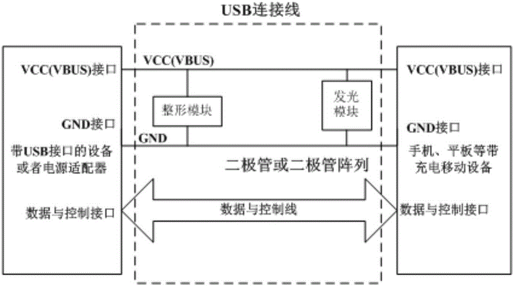
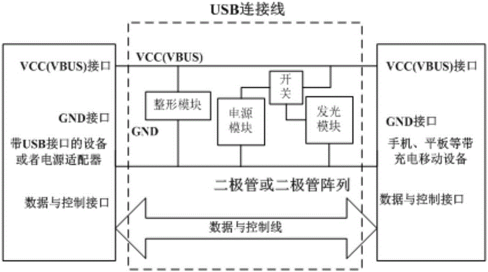
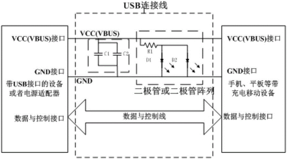
[0046] Such as figure 1 As shown, a preferred embodiment of the present invention provides a USB data cable, which includes a power cable, a ground cable and a data cable, and also includes a USB interface terminal and a data cable body. The USB interface terminal includes a light emitting module for Provide lighting; power shaping module to process the power; wherein, the light emitting module and the power shaping module are connected in parallel with the power line and the ground wire. USB is a commonly used PC interface, with only 4 wires, two power and two signals, so the signals are transmitted serially, and the USB interface is also called a serial port.
[0047] Through this setting, using the power supply network VCC or VBUS (Type-C) and GND network on the USB interface, using the light-emitting module, LED indicators can be added to the two ports of the USB data cable to provide lighting in a dark environment.
[0048] Such as figure 2 As shown, the USB data cable also includes a built-in power module to supply power to the light-emitting module when the data cable is separated from the charger; and a switch. The switch is connected to the light-emitting module, and the switch can be freely switched between the closed state and the open state; The switch is connected to the built-in power module in the closed state; the switch is connected to a power cord of the USB interface in the open state.
[0049] Through this setting, a built-in power module is added, so that the USB data cable can provide lighting without relying on a charger or device, and the switch can control whether to use the built-in power module, so that it can be independently selected according to the situation in actual applications, which is more flexible and convenient.
[0050] Such as image 3 As shown, in this embodiment, the power shaping module includes a capacitor component, and the capacitor component is formed by connecting capacitors C1 and C2 in parallel to stabilize and filter the power supply. C1=10uF, C2=0.1uF. The light-emitting module includes a current-limiting resistor component and a diode component, and the current-limiting component is connected in series with the diode component. The current-limiting resistor component is a current-limiting resistor R1, and the diode component is composed of light-emitting diodes D1 and D2 in parallel.
[0051] With this arrangement, it is possible to provide simple plug-and-bright lighting without a data cable built-in power module.
[0052] Another preferred embodiment of the present invention provides a USB data cable, which is different from the above-mentioned embodiment in:
[0053] Such as Figure 4 As shown, the power shaping module includes a capacitor component, which is formed by connecting capacitors C3 and C4 in parallel to stabilize and filter the power supply. C3=10uF, C4=0.1uF. The light-emitting module includes two LED branches, which are connected in parallel with each other; one LED branch is connected in series by a light-emitting diode D3 and a current-limiting resistor R2, and the other LED branch is formed by a light-emitting diode D4 and a current-limiting resistor. The resistor R3 is connected in series. The power module is composed of a miniature button battery VBAT=3.6V and a voltage divider resistor R4 located in the built-in power supply branch. R4 is used as the voltage divider and current limiting resistor when the LED is built-in power supply.
[0054] With this arrangement, when the data cable is separated from the charger, the built-in power module can be used to power the light-emitting module. The switch can control the choice of LED power supply.
[0055] Such as Figure 5 As shown, two light emitting diodes 1 are symmetrically arranged on the same side surface of the female interface of the USB interface end. Such as Image 6 As shown, the built-in power supply 3 is arranged on the USB interface end, adjacent to the part connected with the data line. Such as Figure 7 As shown, switch 4 is a sliding single-pole double-throw switch.
[0056] The specific manufacturing process is as follows: In one embodiment, D1/D2 are two 0603 packaged light emitting diodes, which are connected in series with the current limiting resistor R1 after being connected in parallel, and the entire light emitting module is located between the power line and the ground line. Make capacitors and resistors on a small board (see Figure 5 ), the reserved connection pads on the small board are used to realize electrical connection; the LED is connected to the small board through a wire or FPC, the purpose is to facilitate the installation of the LED in the designated position of the USB; the USB data cable female header, the wire of the data cable (Power line/ground line, data transmission line) and the small board pad are electrically connected by welding. The technical scheme of the invention has the advantages of simple circuit, low cost, flexibility and easy production, no change to the USB cable and the like.
[0057] In another embodiment, D3/D4 are 0603 packaged light-emitting diodes. The diodes can be fabricated on the upper and lower sides of the female interface of the USB cable. There are two diodes on each side. The surfaces are distributed symmetrically. The positions are as Figure 7 Shown. The power module is composed of a miniature button battery VBAT=3.6V and R4 is located in the built-in power supply branch. R4 is used as the voltage divider and current limiting resistor when the LED is built-in power supply. SW is a sliding single pole double throw switch. The built-in power supply VBAT is connected in series with the resistor R4, and the two 0603 diodes D3/D4 are connected in series with R2/R3 and then connected in parallel. The light-emitting module is connected in series with the switch SW to the USB power line or the built-in power supply. When the switch slides to the corresponding position, the LED is used Powered by USB power cord or built-in battery. Make capacitors, resistors, and built-in switches on a small board (see Image 6 ), and the built-in power supply is installed on the USB interface, adjacent to the part connected with the data line. Make a cover on the USB to facilitate battery replacement, and the switch SW is installed on the side of the USB data cable, such as Figure 7 As shown, slide different positions to choose not to use the power supply. The small board has reserved pads for electrical connection; the LED is connected to the small board through a wire or FPC, the purpose is to facilitate the installation of the LED in the designated position of the USB (see Image 6 ); The electrical connection between the USB data line female header, the data line wires (power line/ground line, data transmission line) and the small board pad is completed by welding.
[0058] Compared with the prior art, the technical solution of the present invention has the following beneficial effects:
[0059] This technical solution uses the characteristics defined by the USB interface to design an indicator light on the data line to facilitate people to charge. The USB data cable of the present invention solves the technical problem of convenient use of USB charging in a dark environment, is simple and practical, has low cost, and takes into account the flexibility of use and the diversity of application scenarios.
[0060] Although the present invention has been disclosed as above in preferred embodiments, it is not intended to limit the present invention. Any person skilled in the art can use the methods and technical content disclosed above to improve the present invention without departing from the spirit and scope of the present invention. The technical solution makes possible changes and modifications. Therefore, all simple modifications, equivalent changes and modifications made to the above embodiments according to the technical essence of the present invention without departing from the content of the technical solution of the present invention belong to the technical solution of the present invention. protected range.