Image switching splicing display system and display method based on data bus interconnection

A splicing display and data bus technology, applied in the direction of image communication, TV system parts, color TV parts, etc., can solve the problem of image display asynchrony, overcome decoding delay, improve quality, and solve IP decoding splicing Out of sync effect

Active Publication Date: 2019-06-07
四川艾之普电子有限责任公司
View PDF4 Cites 0 Cited by
  • Summary
  • Abstract
  • Description
  • Claims
  • Application Information

AI Technical Summary

Problems solved by technology

[0003] The purpose of the present invention is to overcome the defect that the current video image switching splicing display system uses network switching to exchange and process image signals, which may easily lead to asynchronous image display, and to provide an image switching splicing display system based on data bus interconnection and its display method

Method used


Image

  • Image switching splicing display system and display method based on data bus interconnection
  • Image switching splicing display system and display method based on data bus interconnection
  • Image switching splicing display system and display method based on data bus interconnection

Examples


Embodiment 1

[0027] The method for switching and splicing video signals by the image switching splicing display system based on data bus interconnection of the present invention mainly includes the following steps:

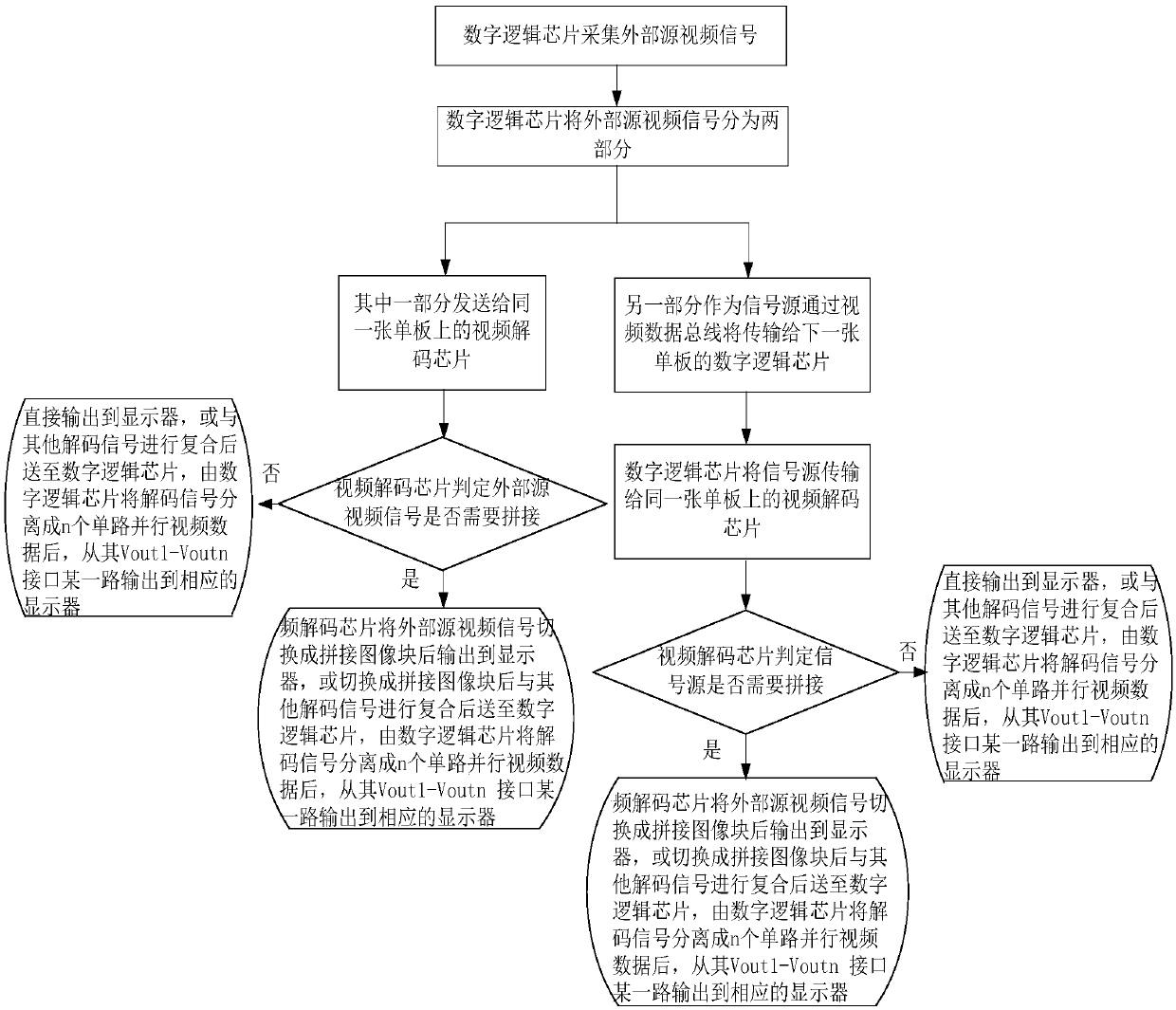
[0028] (1) Collect the video signal output by the network camera or the video signal of the external source.

[0029] (2) Determine whether the video signal output by the network camera or the external source video signal needs to be spliced ​​according to the system requirements; when splicing is not required, the video signal is directly output to the display. When splicing is required, the video signals are switched and spliced ​​and then output to the display.

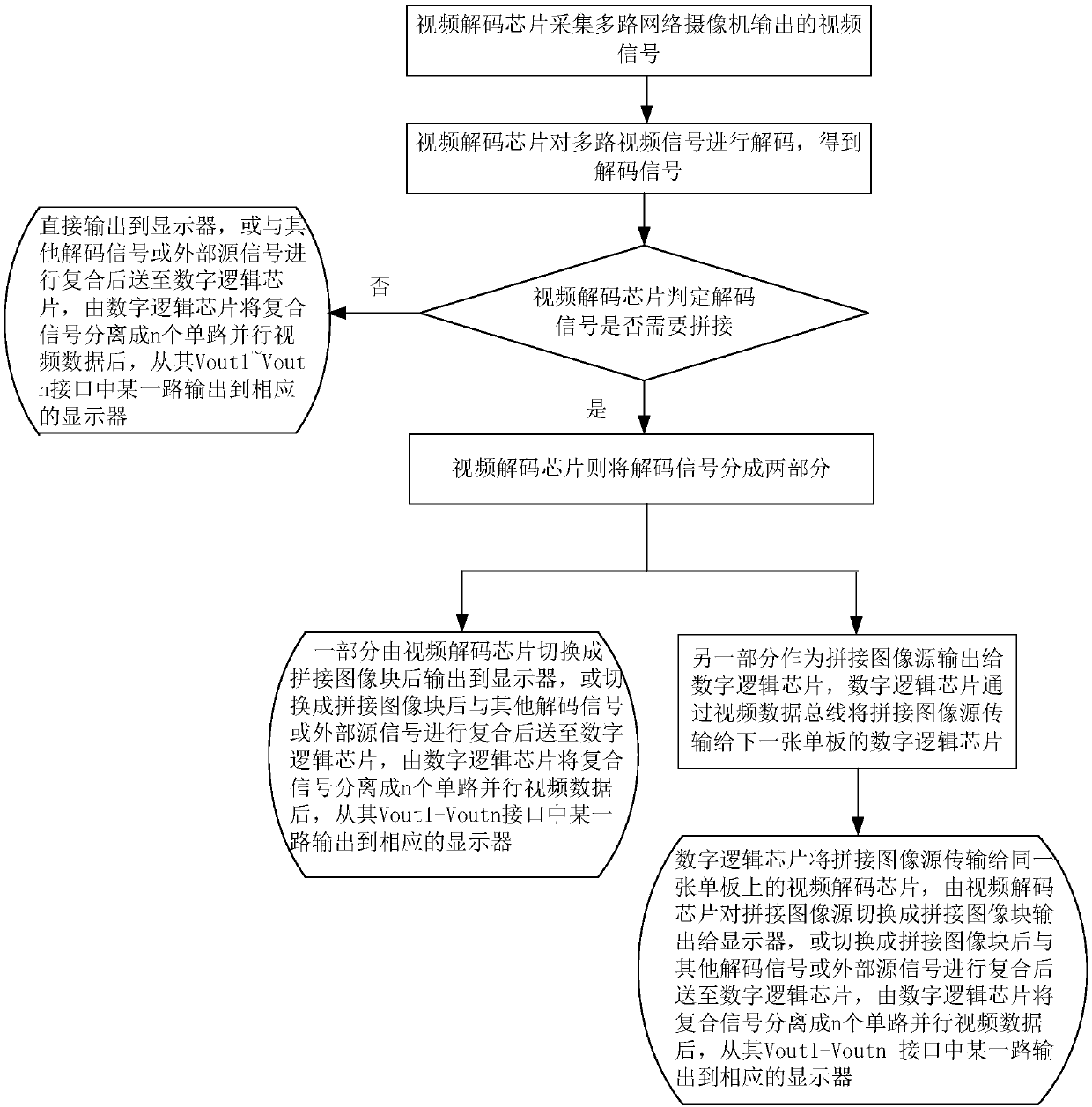
[0030] Such as figure 2 As shown, the switching and stitching method when the video signal collected in the step (1) is the video signal output by the network camera comprises the following steps:

[0031] (1) The video decoding chip collects video signals output by multiple network cameras.

[0032] (2) The vi...

Embodiment 2

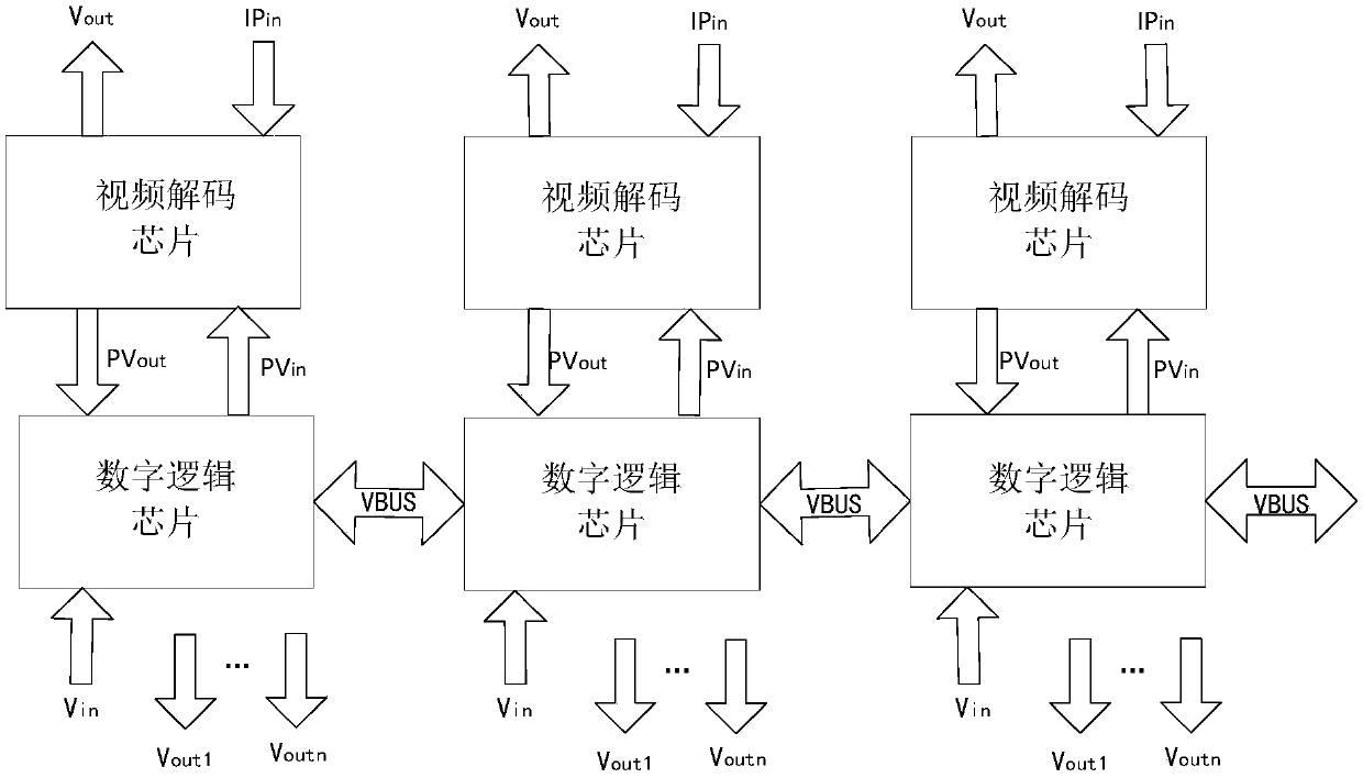
[0040] Such as figure 1 As shown, the image switching splicing display system based on data bus interconnection of the present invention is mainly composed of several single boards, and the adjacent two single boards are connected by the video data bus VBUS; the single board is provided with The digital logic chip is more than one video decoding chip connected with the digital logic chip; the digital logic chips on every two adjacent boards are connected through the video data bus VBUS.

[0041] Wherein, the video decoding chip is used for collecting video signals, decoding or switching the video signals into spliced ​​image blocks, and outputting the decoded video decoded signals or switched spliced ​​image blocks to the display. The logic chip can receive the external source video signal, and send the external source video signal to the video decoding chip on the same board, or send it to the logic chip on the next board to be spliced, and at the same time accept the signal ...


PUM


Abstract

The invention discloses an image switching tiled display system based on data bus interconnection. The image switching tiled display system is characterized by comprising multiple veneers, wherein two adjacent veneers are connected by a video data bus VBUS. Meanwhile, the invention further discloses an image switching tiled display method based on the data bus interconnection. The image switching tiled display method is characterized by comprising the following steps: (1) collecting video signals; and (2) judging whether the video signals requires splicing according to system requirements, if not, directly outputting the video signals to a display; and if so, switching and splicing the video signals, and outputting the same to the display. In a network switching splicing mode, the delay reaches several hundreds of MS and even several sends, by adoption of the image switching tiled display system and method provided by the invention, the splicing delay can be reduced within 30MS, and thus the problem of splicing desynchrony of IP decoding is solved.

Description

technical field [0001] The invention relates to the field of image display, in particular to an image switching and splicing display system based on data bus interconnection and a display method thereof. Background technique [0002] In terms of network camera (IPC) decoding video image switching and splicing display, most of the existing technologies are exchanged and processed based on network switching, that is, each splicing display in the system corresponds to a decoding chip. At this time, the network switching system distributes the signal source of the same IPC to the decoding chip corresponding to the screen that needs to be spliced ​​through the network, decodes the image through different decoding chips, and cuts the corresponding splicing image according to the splicing requirements output to achieve image stitching. When the above method is used for processing, due to the limitation of network conditions, the distribution of image data on the network will cause...

Claims


Application Information

Patent Timeline
Patent Type & Authority Patents(China)
IPC IPC(8): H04N5/268H04N5/265H04N19/44
CPCH04N5/265H04N5/268H04N19/44
Inventor 李杰
Owner 四川艾之普电子有限责任公司
Why Eureka
Try Eureka