
Optimized sound field imaging positioning method and system

A sound field and imaging technology, applied in positioning, radio wave measurement systems, transducer circuits, etc., can solve problems such as inability to effectively image the sound field, adjust the analysis frequency, etc., and achieve improved convenience, improved accuracy, and outstanding convenience Effect

Active Publication Date: 2017-03-08
SHANGHAI KEYGO TECH CO LTD
View PDF5 Cites 7 Cited by
  • Summary
  • Abstract
  • Description
  • Claims
  • Application Information

AI Technical Summary

Problems solved by technology

[0006] Aiming at the deficiency that the existing microphone array sound field imaging technology cannot quickly adjust the analysis frequency according to the situation of the sound field, resulting in the inability to effectively image the sound field, the present invention proposes an optimized sound field imaging positioning method and system. Frequency conversion to obtain and analyze the change rule of frequency and time, and use it as a parameter to automatically set the analysis frequency. The present invention can visually display the characteristics of the current sound field at different frequencies for engineers to quickly locate the sound source

Method used


Image

  • Optimized sound field imaging positioning method and system
  • Optimized sound field imaging positioning method and system
  • Optimized sound field imaging positioning method and system

Examples


Embodiment 1

[0027] This embodiment includes the following steps:

[0028] Step 1, build an optimized sound field imaging positioning system, the system includes: a microphone array, an image acquisition device, a data processing module and a display module, wherein: the data processing module receives the multi-channel sound pressure signal samples output by the microphone array and the image acquisition device and For video information, the sound field video is generated by extracting the sound field state from the multi-channel sound pressure signal samples and merging it with the video information.

[0029] Step 2, collecting multi-channel sound pressure signal samples and video signals.

[0030] Step 3. According to the time-domain waveform characteristics of the sound pressure signal, an appropriate time-frequency analysis method is selected.

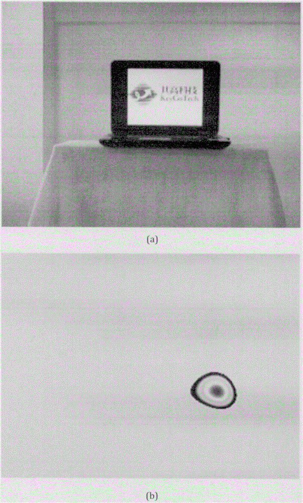
[0031] Such as figure 1 As shown, it is the result of time-frequency analysis of the sound pressure signal sample. From the analysis result...

Embodiment 2

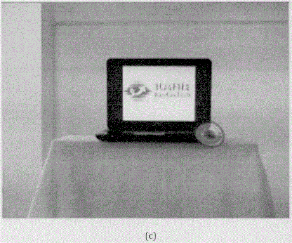
[0043] Figure 4 It is a block diagram of an optimized sound field imaging positioning system 100 according to an embodiment of the present invention. Such as Figure 4 As shown, the optimized sound field imaging positioning system 100 includes: a microphone array 102 is used to collect sound pressure signals of the sound field, an image acquisition device 104 is used to collect optical images of the sound field, and a data processing module 106 is connected with the microphone array 102 and the sound field respectively. The image acquisition device 104 is connected to receive the multi-channel sound pressure signal samples and video information output by the microphone array 102 and the image acquisition device 104 respectively, by extracting the sound field state from the multi-channel sound pressure signal samples After combining with the optical image, an optimized sound field image is generated, and the display module 108 is used to display the sound field image. The da...


PUM


Abstract

The invention discloses an optimized sound field imaging positioning method and system. Multi-channel sound field samples synchronous with a video are collected by employing a microphone array; time frequency distribution characteristics of the sound field samples are obtained from the sound field samples; a corresponding relationship between time information and analysis frequency is obtained according to time frequency distribution; a sound field state corresponding to analysis time and the analysis frequency is obtained according to the corresponding relationship; and the sound field state and the video are integrated in a cloud chart mode, thereby realizing sound field imaging. According to the method and the system, concrete positions of a plurality of sound sources and the attributes of different sound bands of the various sound sources can be obtained visually and rapidly.

Description

technical field [0001] The present invention relates to a technology in the field of audio and image processing, specifically a method and system for optimizing sound field imaging and positioning, which can accurately obtain the imaging frequency band range corresponding to the current sound signal, and quickly and dynamically realize the setting of frequency band range parameters . Background technique [0002] Microphone array technology uses microphones distributed in space to pick up sound signals, and then uses signal processing technology to analyze and process the picked up sound signals, measure the spatial distribution information of the sound source, reproduce the sound field, and synthesize it with the optical image , the sound source can be imaged, and it is convenient to intuitively obtain the position of the sound source in the sound field, the sound pressure distribution and other information. In the actual detection process, the frequency spectrum of the so...

Claims


Application Information

Patent Timeline
IPC IPC(8): H04R3/00G01S5/18
Inventor 吴郁程张南雄
Owner SHANGHAI KEYGO TECH CO LTD
Learn More