Rotary distributing device

A technology of rotating distribution device and driving device, which is applied to spray devices, liquid spray devices, spray devices with movable outlets, etc. The effect of angle synchronization

Inactive Publication Date: 2017-03-15
广州轻机机械设备有限公司
View PDF11 Cites 0 Cited by
  • Summary
  • Abstract
  • Description
  • Claims
  • Application Information

AI Technical Summary

Problems solved by technology

[0006] In order to solve the problem that the existing cleaning equipment and disinfection equipment cannot realize the mixing of gas and liquid when it is close to spraying, and cannot achieve the high efficiency of gas-liquid mixing and ready-to-use, the present invention provides a cleaning and disinfection equipment Rotary distribution device

Method used


Image

  • Rotary distributing device
  • Rotary distributing device
  • Rotary distributing device

Examples


Embodiment 1

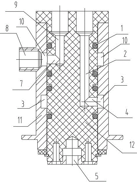
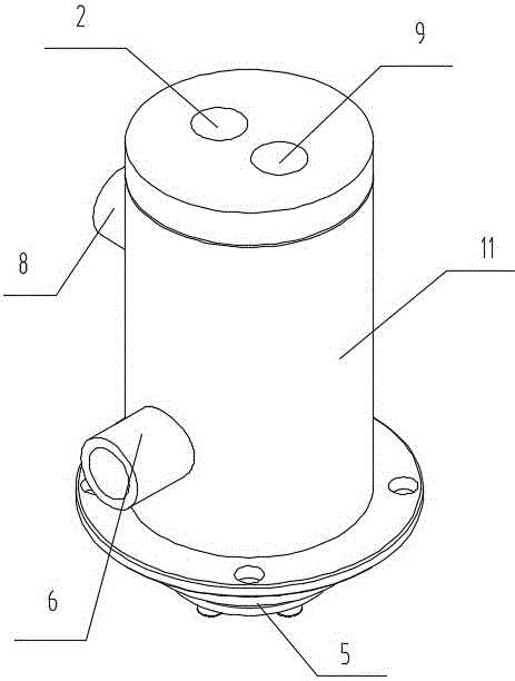
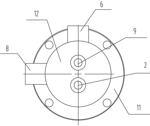
[0033] Such as figure 1 , 2 , 3 and 4 shown in the rotary distribution device, including a cylindrical shell 11 and a cylindrical core 12. The lower central axis of the inner core 12 is connected with the motor 5, and the motor 5 drives the inner core 12 to rotate inside the shell. The motor 5 is controlled by the control system to enhance the controllability of the motor. The cylindrical inner core 12 can have the largest contact area with the outer wall of the outer shell 11, and the inner core 12 is less likely to shake when it rotates in the outer shell.

[0034] A liquid inlet pipe 6 and an air inlet pipe 8 are arranged on the casing 11 . The liquid inlet pipe 6 is arranged below the air inlet pipe 8 . The liquid inlet pipe 6 is connected with an annular liquid delivery chamber 3 arranged inside the shell 11, and the annular liquid delivery chamber 3 is connected with a liquid delivery horizontal pipe 4 arranged in the inner core 12, and the liquid delivery horizontal...

Embodiment 2

[0042] In Embodiment 1, the liquid inlet pipe 6 is arranged horizontally, and forms an included angle of 60 to 75 degrees with the tangent direction of the connection point of the outer wall of the annular liquid delivery chamber 3, so that the liquid flows in the same direction in the annular liquid delivery chamber 3 when entering the liquid. , and form a centripetal force to move closer to the inner wall of the annular liquid delivery chamber 3, making it easier for the liquid to flow into the liquid delivery horizontal tube 4 arranged in the annular liquid delivery chamber 3, improving the efficiency of liquid delivery. The cross-sectional areas of the liquid inlet pipe 6 and the air inlet pipe 8 are larger than those of the liquid outlet pipe 2 and the air outlet pipe 9 respectively. The motor 5 in Embodiment 1 replaces the air motor.

Embodiment 3

[0044] In Example 1, the liquid feeding channel formed by connecting the liquid inlet pipe 6 , the annular liquid feeding chamber 3 , the liquid feeding horizontal pipe 4 , and the liquid outlet pipe 2 . The number of liquid delivery channels is greater than or equal to 2, that is, there are multiple liquid delivery channels. Some mixtures need to be prepared and used immediately to exert good disinfection and cleaning effects. If multiple substances are mixed in advance or mixed with air in advance, oxidation-reduction reactions will occur with each other and their performance will be reduced. When multiple liquids are required to be mixed at the spray head 16 , only a plurality of liquid delivery channels need be provided, and at this time, only a plurality of annular liquid delivery chambers 3 and annular air delivery chambers 10 are only required to be separately provided on the housing 11 . Corresponding horizontal liquid-feeding pipes 4 and liquid-outlet pipes 2 connecte...


PUM


Abstract

The invention belongs to cleaning and sterilizing equipment in the field of cleaning and sterilizing, and relates to a rotary distributing device. The rotary distributing device comprises a shell and an inner core positioned in the shell, and is characterized in that the shell or the inner core is connected with a driving device, so that one of the shell and the inner core becomes a rotating piece, and the other one becomes a fixed piece; annular air delivering cavities and annular liquid delivering cavities are formed in a position where the shell is connected with the inner core in the peripheral direction; sealing bodies are arranged on the periphery of each annular liquid delivering cavity and the periphery of each annular air delivering cavity; the rotating piece is provided with air outlet tubes and liquid outlet tubes; the fixed piece is provided with air inlet tubes and liquid inlet tubes; each air inlet tube, the corresponding annular air delivering cavity and the corresponding air outlet tube communicate with one another; each liquid inlet tube, the corresponding annular liquid delivering cavity and the corresponding liquid outlet tube communicate with one another; and each air outlet tube and the corresponding liquid outlet tube are connected with the same sprayer. By the rotary distributing device, the problems that by existing cleaning equipment and existing sterilizing equipment, air and liquid cannot be mixed when the air and the liquid are about to be sprayed out, and high efficiency of using during distributing cannot be achieved are solved.

Description

technical field [0001] The invention belongs to cleaning and disinfection equipment in the field of cleaning and disinfection, in particular to a rotary distribution device. Background technique [0002] In the fields of food, medicine and dairy products, bacteria are easy to breed, and it is difficult to remove all bacteria with simple disinfection and cleaning. Residual bacteria grow exponentially and cause great harm to production. In-depth, high-level cleaning and disinfection of the production environment and production equipment used can ensure the safety of food, dairy products and pharmaceuticals. Many domestic manufacturers use manual cleaning to achieve the purpose of cleaning and disinfection, but the efficiency of manual work is low and the cost is high. [0003] However, the existing automatic cleaning equipment is difficult to meet the deep-seated and high-level cleanliness requirements in the fields of food, medicine and dairy products. For example, an auto...

Claims


Application Information

Patent Timeline
Patent Type & Authority Applications(China)
IPC IPC(8): B05B7/04B05B7/08B05B3/10B05B12/14
CPCB05B3/1007B05B3/1042B05B7/0408B05B7/0416B05B7/08B05B12/1418
Inventor 沈利君刘尉张新野陈泽彬刘林森
Owner 广州轻机机械设备有限公司
Why Eureka
Try Eureka