Cone and cone hole machining method

A processing method and cone technology, which is applied in the field of marine propellers and stern shafts, can solve problems such as the inability to fundamentally meet the requirements of contact area and roughness, low efficiency of the assembly process, and high maintenance costs, so as to save assembly time , production efficiency improvement, and the effect of large contact area

Active Publication Date: 2017-03-15
ZHUHAI HOLYFORT MARINE EQUIP CO LTD
View PDF4 Cites 6 Cited by
  • Summary
  • Abstract
  • Description
  • Claims
  • Application Information

AI Technical Summary

Problems solved by technology

The traditional mating process has low efficiency and low quality, and cannot fundamentally meet the requirements of contact area and roughness, and has poor interchangeability
At present, whenever a ship’s propeller is damaged and needs to be replaced, the stern shaft must be removed from the ship and transported to the scraping workshop for scraping and matching with the newly made propeller. This method has a large workload, a long cycle, and high maintenance costs, and urgently needs to be improved.
In summary, it is necessary to improve the manufacturing method of the propeller cone hole to solve the problems of complicated operation, low efficiency, high cost and poor interchangeability in the prior art

Method used


Image

  • Cone and cone hole machining method
  • Cone and cone hole machining method
  • Cone and cone hole machining method

Examples


Embodiment Construction

[0025] see Figure 1 to Figure 6 , a kind of processing method of taper body and taper hole, this method comprises the following steps:

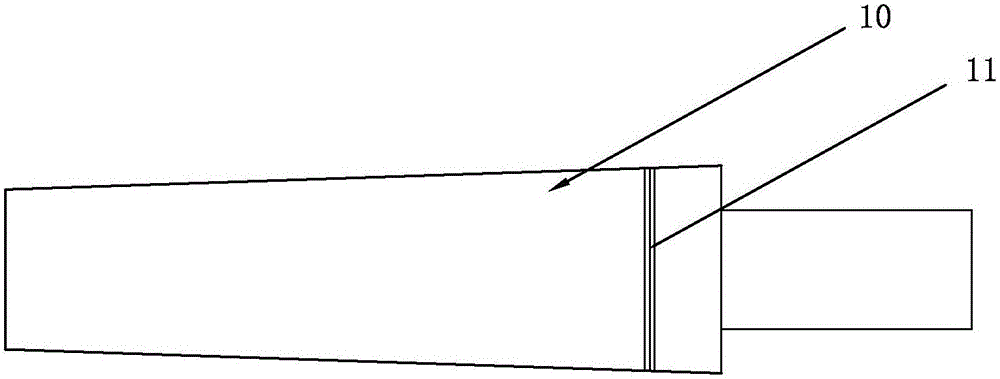
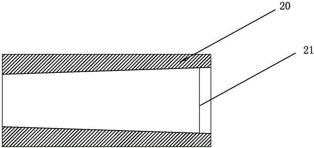
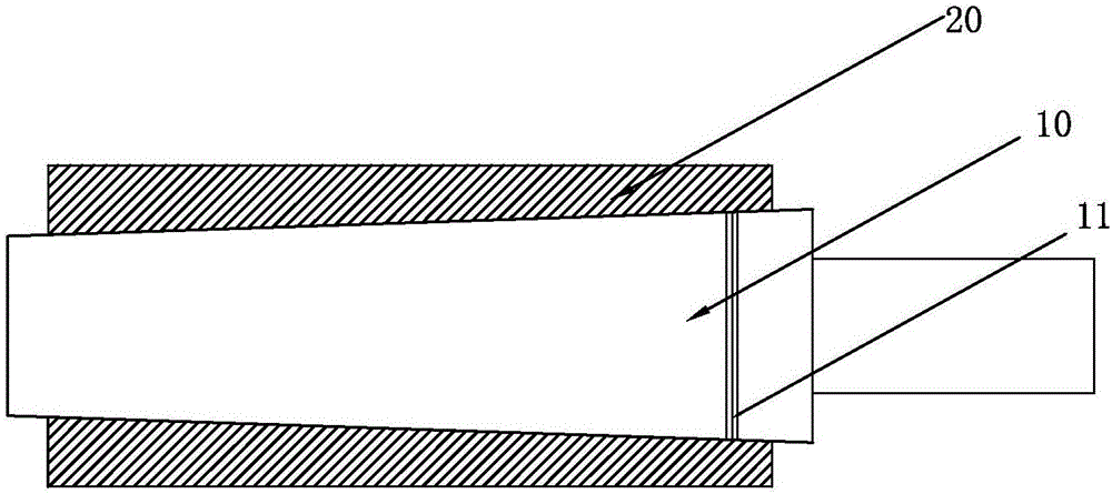
[0026] Step 1: making a taper sleeve 20 and a taper rod 10, the taper rod 10 and the taper sleeve 20 are manufactured according to the same taper, and after grinding, the contact area between the two accounts for more than 95% of the cone matching ratio;

[0027] Step 2: The taper rod 10 draws a first marking line 11 at a position equal to the standard diameter value of the large end of the preset propeller taper hole 30, and the taper sleeve 20 draws a second marking line 21 at a position equal to the above-mentioned standard diameter;

[0028] Step 3: making the propeller cone 30 and the stern shaft cone 40, the length of the propeller cone 30 is correspondingly less than the length of the taper rod 10 cone, and the length of the stern cone 40 is correspondingly less than the length of the taper sleeve 20 cone;

[0029] Step 4: Process th...


PUM


Abstract

The invention discloses a cone and cone hole machining method. The method comprises the steps that a taper rod and a taper sleeve which are same in taper are made, wherein the cone matching contact area reaches 95% or above; a first marking line is drawn on the portion, with the diameter equal to a standard diameter value of the big end of a preset propeller cone hole, of the taper rod, and a second marking line is drawn on the portion, with the diameter equal to the above-mentioned standard diameter, of the taper sleeve; a propeller cone hole and a screw shaft cone are made, wherein the length of the propeller cone hole is correspondingly smaller than the cone length of the taper rod, and the length of the screw shaft cone is correspondingly smaller than the cone hole length of the taper sleeve; and when the propeller cone hole and the screw shaft cone are machined, the taper rod and the taper sleeve are adopted for replacing the corresponding screw shaft cone and propeller cone hole to check the contact area of the taper rod and the propeller cone hole and the contact area of the taper sleeve and the screw shaft cone and the cone size. The invention provides an efficient propeller cone hole machining method. The method is high in machining precision, good in cone matching contact surface, easy to operate, good in interchangeability, capable of saving labor and low in manufacturing cost.

Description

technical field [0001] The invention relates to the technical field of marine propellers and stern shafts, in particular to a method for processing cones and taper holes. Background technique [0002] At present, the traditional process route of propeller cone hole processing is as follows: firstly, use a lathe to roughly process the propeller cone hole, leaving a scraping allowance of 0.5mm in diameter, and then use a scraper or a small grinding wheel to manually grind the propeller shaft. Carry out the matching, and control the number of contact spots to achieve the control of the contact area. With the development of large-scale ships, the diameter and length of the propeller cone hole are getting larger and larger, and more and more keyless connections between the propeller cone hole and the propeller shaft are used, and there are higher requirements for the contact surface and roughness of the cone. . The traditional mating process has low efficiency and low quality, ...

Claims


Application Information

Patent Timeline
Patent Type & Authority Applications(China)
IPC IPC(8): B23P15/00
CPCB23P15/00
Inventor 吴堂堂王成军刘子洋
Owner ZHUHAI HOLYFORT MARINE EQUIP CO LTD
Why Eureka
Try Eureka