High Efficiency Pantograph

Inactive Publication Date: 2019-01-29
张雨薇
View PDF5 Cites 1 Cited by
  • Summary
  • Abstract
  • Description
  • Claims
  • Application Information

AI Technical Summary

Problems solved by technology

[0002] The pantograph is the electrical equipment used by the electric traction locomotive to obtain electric energy from the catenary. It is installed on the roof of the locomotive or motor car; Rod, chassis, lifting bow spring, transmission cylinder, supporting insulator and other components; the current receiving quality of the pantograph is related to the following factors: contact pressure between the pantograph slide plate and the catenary, transition resistance, contact area, etc. ; Therefore, in order to ensure the smooth flow of traction current, a certain pressure must be maintained between the pantograph and the contact wire; the current commonly used pantograph has a complex structure and high maintenance costs. Pressing the catenary to maintain the pressure, this structure has an excessive burden on the catenary, affecting the firmness and stability of the catenary

Method used


Image

  • High Efficiency Pantograph
  • High Efficiency Pantograph
  • High Efficiency Pantograph

Examples


Embodiment

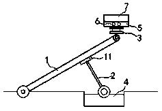
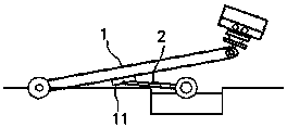
[0021] exist Figure 1 to Figure 4 In the shown embodiment, the high-efficiency pantograph includes a connecting rod 1 and a strut 2,

[0022] One end of the connecting rod 1 is hingedly mounted on the top plate of the train, and the other end of the connecting rod 1 is fixedly equipped with a telescopic arm 3, and the telescopic arm 3 is controlled to expand and contract by the electrical system;

[0023] A slider 11 is installed on the connecting rod 1, and the slider 11 can reciprocate and translate along the axis direction of the connecting rod 1; one end of the rod 2 is hinged on the slider 11, and the other end is installed on the rotating motor 4 On the drive shaft, the pole 2 can rotate synchronously with the drive shaft;

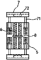
[0024] A slide plate 5 is fixedly installed at the end of the telescopic arm 3, and an induction solenoid 6 is embedded inside the slide plate 5, and the axis of the induction solenoid 6 is perpendicular to the contact line on the catenary;

[002...


PUM


Abstract

The invention relates to a high power pantograph. The pantograph comprises a connecting rod and a support rod. The connecting rod is provided with a slide block. One end of the support rod is connected with the slide block in hinged mode. The other end of the support rod is placed on a drive shaft of a rotation motor. One end of a telescopic arm is fixedly provided with a slide plate. Inductive solenoids are embedded in the slide plate. The axial line of each inductive solenoid is perpendicular to a contact line of a contact grid. Both the left and right sides of the slide plate are provided with clamp plates. The clamp plates are connected with the slide plate through slide bars. One end of each slide bar is fixedly installed on the clamp plate. The other end of the slide bar extends into the slide plate. A permanent magnet is embedded in the side surface of each inductive solenoid just opposite to the clamp plate. Circuit breakers are placed in all inductive solenoids, and are connected in serial mode. The pantograph has the novel and peculiar structure, can keep enough pressure between the pantograph and the contact grid, at the same time causes no big burden to the contact grid, thus protecting the contact gird in an effective manner, and enhancing the quality of current influx.

Description

technical field [0001] The invention relates to a train assembly, in particular to a pantograph. Background technique [0002] The pantograph is the electrical equipment used by the electric traction locomotive to obtain electric energy from the catenary. It is installed on the roof of the locomotive or motor car; Rod, chassis, lifting bow spring, transmission cylinder, supporting insulator and other components; the current receiving quality of the pantograph is related to the following factors: contact pressure between the pantograph slide plate and the catenary, transition resistance, contact area, etc. ; Therefore, in order to ensure the smooth flow of traction current, a certain pressure must be maintained between the pantograph and the contact wire; the current commonly used pantograph has a complex structure and high maintenance costs. Pressing the catenary to maintain the pressure, this structure will produce an excessive burden on the catenary, affecting the firmnes...

Claims


Application Information

Patent Timeline
Patent Type & Authority Patents(China)
IPC IPC(8): B60L5/28
CPCB60L5/28B60L2200/26
Inventor 钱月珍
Owner 张雨薇
Why Eureka
Try Eureka