Clothes dryer and control method thereof

A dryer and air duct technology, applied in household dryers, textiles and papermaking, washing devices, etc., can solve problems such as the loss of clothes dryers and other indoor components, achieve suitable promotion and use, eliminate peculiar smells, and have remarkable effects Effect

Inactive Publication Date: 2017-03-15
QINGDAO HAIER WASHING MASCH CO LTD
View PDF10 Cites 27 Cited by
  • Summary
  • Abstract
  • Description
  • Claims
  • Application Information

AI Technical Summary

Problems solved by technology

[0005] However, due to the current heat pump dryers on the market, they only use the circulating airflow to dry the clothes inside the outer cylinder through the above-mentioned method.
[0006] At the same time, clothes dryers are generally installed in rooms with high humidity such as the user's toilet. In the case of high humidity in the external space, it is easy to cause damage to the clothes dryer and other indoor components.

Method used


Image

  • Clothes dryer and control method thereof
  • Clothes dryer and control method thereof
  • Clothes dryer and control method thereof

Examples


Embodiment 1

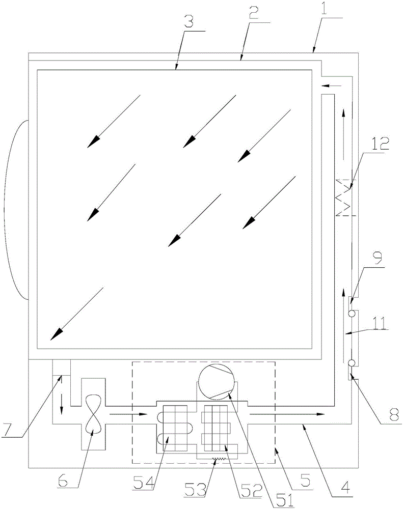
[0047] Such as figure 2 As shown, in this embodiment, the air intake door 9 and the air outlet door 8 divide the circulating air path into the first air path 10 and the second air path 11; the evaporator 54 and the condenser 52 are located at the same In the first air passage 10 , and the evaporator 54 is arranged away from the air outlet damper 8 relative to the condenser 52 .

[0048] In this embodiment, the second air path 11 is provided with an openable and closable partition, so that the external airflow flowing into the circulating air path from the air inlet door 9 all flows along the first air path 10 to the air outlet door. 8, instead of flowing through the second air path 11 to the air outlet damper 8, it is ensured that the inhaled external air is dehumidified by the heat pump system, and the dehumidification efficiency of the clothes dryer is improved.

[0049] Such as figure 2 As shown, in this embodiment, the air inlet door 9 and the air outlet door 8 are hin...

Embodiment 2

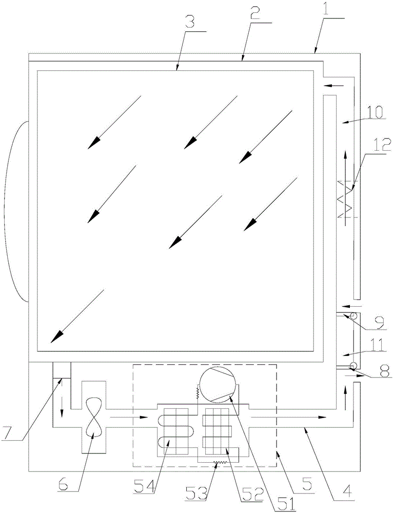
[0054] In this embodiment, the air inlet door 9 and the air outlet door 8 are both arranged at the rear side of the clothes dryer.

[0055] Such as image 3 As shown, in this embodiment, the air inlet door 9 and the air outlet door 8 are both arranged in the drying air duct 4 between the condenser 52 and the air inlet of the outer cylinder 2, and the air inlet door 9 is relatively air outlet. The damper 8 is located away from the condenser 52 . Thus, the external air flows into the drying air duct 4 from the air inlet door 9 at the rear of the dryer, then passes through the outer cylinder 2, the evaporator 54, and the condenser 52 in sequence, and finally reaches the outlet air door at the rear of the dryer. 8 flow out to achieve dehumidification of the external airflow. At the same time, during the dehumidification process, a flowing airflow is formed in the outer cylinder to achieve the effect of eliminating peculiar smell inside the outer cylinder of the clothes dryer.

...

Embodiment 3

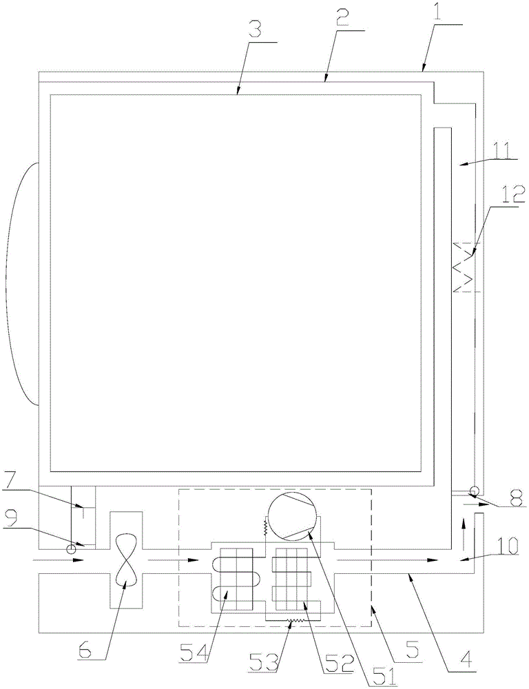
[0058] In this embodiment, the air inlet door 9 is arranged at the front side of the clothes dryer, and the air outlet door 8 is arranged at the back side of the clothes dryer.

[0059] Such as image 3 As shown, in this embodiment, the air inlet damper 9 is arranged in the drying air duct 4 between the air outlet of the outer cylinder 2 and the evaporator 54, and the air outlet damper 8 is arranged at the inlet of the condenser 52 and the outer cylinder 2. In the drying air duct 4 between the tuyere. Thus, the external air flows into the drying air duct 4 from the air inlet door 9 at the front of the clothes dryer, then passes through the evaporator 54 and the condenser 52 in sequence, and finally flows out to the air outlet door 8 at the rear of the clothes dryer, so as to Realize the dehumidification treatment of the external airflow.

[0060] Through the above setting, the external air flowing into the dryer does not pass through the outer cylinder, and is directly disch...


PUM


Abstract

The invention relates to a clothes dryer and a control method thereof; the clothes dryer comprises a circulation air path formed by an outer cylinder and a drying channel, and a heat pump system; an evaporator and a condenser of the heat pump system are arranged in the drying channel so as to respectively condense and heat up flowing circulating airflow; the circulation air path is provided with an air inlet door and an air outlet door controlled to open and close, so the circulation air path can be controlled to connect with or disconnect from the outer side; when the clothes dryer dries the clothes, the air inlet door and the air outlet door are respectively closed, and the circulation airflow in the circulation air path can dry up the clothes in the outer cylinder; when the clothes dryer dehumidifies outer air, the air inlet door and the air outlet door are respectively opened, the outer air continuously enters the circulation air path, and is dehumidified by the evaporator and exhausted, thus dehumidifying the outer air. The device and method allow the clothes dryer to respectively dry up the clothes in the outer cylinder and dehumidify the outer air, thus providing a dehumidifier function.

Description

technical field [0001] The present invention relates to a clothes drying device in the field of household appliances, in particular to a direct discharge heat pump clothes dryer, and also to a control method for the clothes dryer. Background technique [0002] Existing dryers mainly exist in the following two ways: [0003] The first type is a straight-line clothes dryer, and its working principle is as follows: air is sucked in from the outside atmosphere, and the inhaled air is heated by a heating wire, and the heated high-temperature dry air is blown into the outer cylinder, and the clothes Moisture is vaporized; the vaporized water is mixed into the gas to become high-temperature moisture, and the high-temperature moisture is finally discharged out of the outer cylinder to achieve the purpose of drying clothes. However, in the above method, since the exhaust gas contains a large amount of waste heat, it cannot be recycled, resulting in high energy consumption and low ef...

Claims


Application Information

Patent Timeline
Patent Type & Authority Applications(China)
IPC IPC(8): D06F58/20D06F58/28
CPCD06F58/20D06F58/206D06F58/30D06F2103/36D06F2105/24D06F2105/28
Inventor 邴进东路三伟
Owner QINGDAO HAIER WASHING MASCH CO LTD
Why Eureka
Try Eureka