Casing pipe bending induction support provided with circumferential trapezoid induction units

A trapezoidal and circumferential technology, applied to building components, earthquake resistance, building types, etc., can solve the problems of weakening the energy consumption capacity of supports, not conducive to the generation of plastic hinges, and low design flexibility, so as to reduce the workload of wet work, The effect of simple structure and easy support

Active Publication Date: 2017-03-15
SOUTHEAST UNIV
View PDF10 Cites 1 Cited by
  • Summary
  • Abstract
  • Description
  • Claims
  • Application Information

AI Technical Summary

Problems solved by technology

On June 1, 2016, the applicant proposed a casing-constrained buckling-resistant brace with symmetrical initial defects (application number 201610383428.8) and a casing-constrained buckling-resistant brace with diamond-shaped energy dissipation units (application number 201610383133.0) has a fixed geometry and little design flexibility
Moreover, the thickness and structure of the energy-dissipating unit at the crease in the above support are the same as those at the non-crease, which is not conducive to the generation of plastic hinges at the crease.
In addition, these supports are composed of end restraint segments, buckling segments, and sleeves. The sleeves are on the outside of the buckling segment, and there is no support on the inside of the buckling segment, which is prone to low-order instability toward the inside, thereby weakening the energy dissipation capacity of the support.

Method used


Image

  • Casing pipe bending induction support provided with circumferential trapezoid induction units
  • Casing pipe bending induction support provided with circumferential trapezoid induction units
  • Casing pipe bending induction support provided with circumferential trapezoid induction units

Examples


Embodiment Construction

[0028] The present invention will be further described below in conjunction with the accompanying drawings.

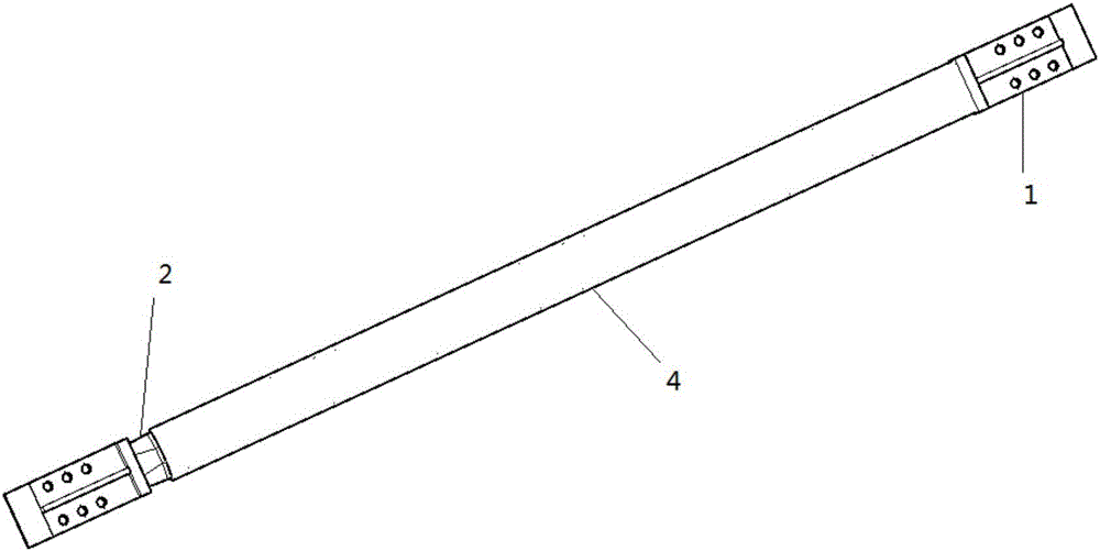
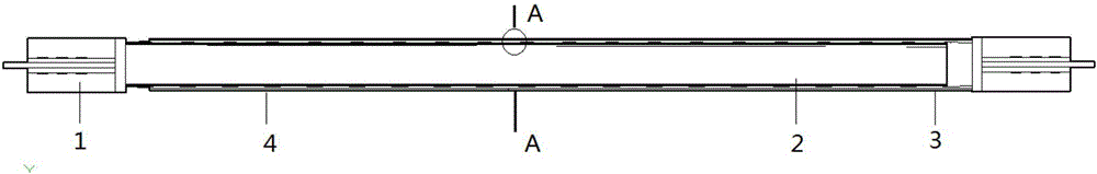
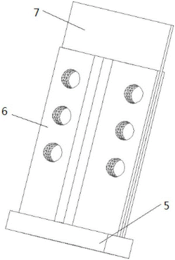
[0029] Such as figure 1 , 2 As shown, it consists of an end restraint section 1, a buckling induction section 2, an inner sleeve 3 and an outer sleeve 4. The end constraining section 1 is fixed at both ends of the buckling inducing section 2 . The left end of the inner sleeve is welded to the square steel plate 5 of the left end restraint section 1, and there is a distance between the right end of the inner sleeve and the square steel plate of the right end restraint section, which is not less than 1 / 40 of the length of the buckling induction section ; The right end of the outer sleeve is welded to the square steel plate 5 of the right end restraint section 1, and there is a distance between the left end of the outer sleeve and the square steel plate of the left end restraint section, and the distance is no less than 1 / 40 of the length of the buckling induction secti...


PUM


Abstract

The invention discloses a casing pipe bending induction support provided with circumferential trapezoid induction units. The casing pipe bending induction support consists of an end restraint section, a bending induction section, an inner casing pipe and an outer casing pipe, wherein the bending induction section is clamped between the inner casing pipe and the outer casing pipe, the inner casing pipe and the outer casing pipe are respectively connected with one end restraint section, and the bending induction section consists of at least one circumferential trapezoid induction unit in the axis direction of the support. The single circumferential trapezoid induction unit is a space body with a polygonal cross section formed by sequentially arranging m same circumferential trapezoid sub-units in the circumferential direction, and the circumferential trapezoid sub-units are space bodies formed by folding four isosceles trapezoidal plates located in a plane. The casing pipe bending induction support retains elasticity under a small shock effect, is at a yielding state under a medium or large shock effect, and the good hysteresis energy dissipation capacity can also play the effect of a damper. The casing pipe bending induction support can be prefabricated in a factory, the working amount of site construction operation is decreased, and the casing pipe bending induction support saves energy and is environmentally friendly.

Description

technical field [0001] The invention belongs to the technical field of building structures, and in particular relates to a casing buckling induction support with a circular trapezoidal induction unit, which is suitable for steel structures or concrete structures with buckling restraint supports. Background technique [0002] During the use of steel structures or reinforced concrete structures, ordinary supports will buckle under compression. When the supports buckle under compression, the stiffness and bearing capacity will decrease sharply. Under the action of earthquake or wind, the internal force of the support changes back and forth under the two states of compression and tension. When the support gradually changes from the buckling state to the tension state, the internal force and stiffness of the support are close to zero. Therefore, the hysteretic performance of ordinary supports is poor under repeated loads. In order to solve the problem of buckling under compress...

Claims


Application Information

Patent Timeline
Patent Type & Authority Applications(China)
IPC IPC(8): E04B1/98E04H9/02
CPCE04H9/021E04H9/024
Inventor 蔡建国冯健周宇航杨海龙柳杨青
Owner SOUTHEAST UNIV
Why Eureka
Try Eureka