
Electromagnetic pin

A technology of electromagnetic pin and magnetic steel, which is applied to the electromagnetic pin. It can solve the problems of high manufacturing cost, high power consumption and large volume of electromagnetic pins, and achieve the effects of reducing power consumption, improving reliability and reducing volume

Active Publication Date: 2017-03-15
GUIZHOU SPACE APPLIANCE CO LTD +1
View PDF5 Cites 0 Cited by
  • Summary
  • Abstract
  • Description
  • Claims
  • Application Information

AI Technical Summary

Problems solved by technology

It solves the problems of high power consumption, large volume and high manufacturing cost of existing electromagnetic pins

Method used


Image

  • Electromagnetic pin

Examples


Embodiment Construction

[0020] The technical solution of the present invention is further described below in conjunction with the accompanying drawings, but the scope of protection is not limited to the description.

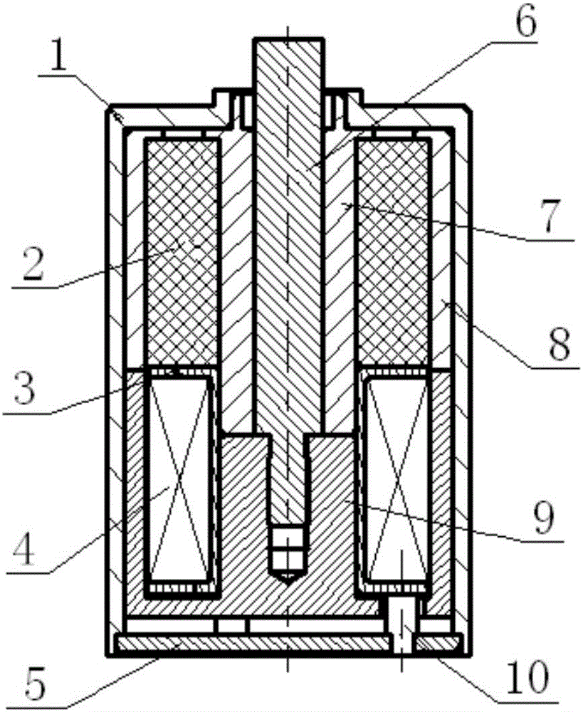
[0021] like figure 1 The shown electromagnetic pin includes a housing 1, a magnetic steel 2, a skeleton 3, a coil 4, a rear cover 5, a mandrel 6, a static iron core 7, a yoke 8, a moving iron core 9, and a pin 10; The magnetic steel 2 is arranged between the static iron core 7 and the yoke 8, the back cover 5 is fixed on the bottom of the housing 1, the pin 10 is installed and fixed on the back cover 5, and one end surface of the skeleton 3 is connected with the magnetic steel 2, The other end face is connected with the pin 10, the coil 4 is wound in the annular groove of the skeleton 3, the moving iron core 9 is movably installed in the central circular hole of the skeleton 3, and the mandrel 6 is movably installed in the static iron core 7 and connected with the moving iron core 9, t...


PUM


Abstract

The present invention discloses an electromagnetic pin. The electromagnetic pin includes a shell, a magnet, a frame, a coil, a rear cover, a mandrel, a fixed iron core, a yoke, a movable iron core and a pin; the magnet is arranged between the fixed iron core and the yoke; the rear cover is fixed onto the bottom of the shell; the pin is installed on the rear cover; one end surface of the frame is connected with the magnet, and the other end surface of the frame is connected with the pin; the coil is wound in the annular groove of the frame; the movable iron core is movably arranged in the center circular hole of the frame; the mandrel is movably mounted in the inner hole of the fixed iron core and is connected with the movable iron core; and the yoke and the movable iron core are arranged in the shell. According to the electromagnetic pin of the invention, the magnet, the fixed iron core, the yoke and the movable iron core form a semi-enclosed magnetic circuit; the annular structure of the movable iron core is in short connection with the polarities at two ends of the magnet, so that a bipolar double-air gap mono-stable structure can be formed; and magnetic energy can be stored by means of the permanent magnet characteristic of the magnet so as to provide a driving force for the movable iron core, and therefore, the magnetic effect of the coil is higher. With the electromagnetic pin adopted, the problems of high power consumption, large size and high manufacturing cost of an existing electromagnetic pin can be solved.

Description

technical field [0001] The invention belongs to the technical field of electromagnetic drive, and in particular relates to an electromagnetic pin. Background technique [0002] At present, the electromagnetic pins currently used in the market are all realized by a single electromagnetic drive structure, and there are the following deficiencies in the use process: (1) the existing electromagnetic pins start to do the pull-in action, and the starting power consumption is large; (2) the existing electromagnetic pins The action of the electromagnetic pin is usually driven by a single coil, and the volume is relatively large; (3) the existing electromagnetic pin has many consumables and high manufacturing costs. [0003] For example, the Chinese patent with the publication number CN2457721Y discloses a permanent magnet operating mechanism, which consists of a yoke, a double clapping surface movable armature, an annular boss on the outer wall of the inner yoke, a conical magnetic ...

Claims


Application Information

Patent Timeline
IPC IPC(8): H01H3/28
CPCH01H3/28
Inventor 李国强
Owner GUIZHOU SPACE APPLIANCE CO LTD
Learn More