Network IP address automatic distribution method

An IP address, automatic allocation technology, applied in the network field, can solve the problems of terminal equipment offline, IP address allocation conflicts, offline and mutual preemption of IP addresses, etc., to increase reliability and overcome IP allocation conflicts.

Active Publication Date: 2017-03-15
XIAN NOVASTAR TECH
View PDF4 Cites 9 Cited by
  • Summary
  • Abstract
  • Description
  • Claims
  • Application Information

AI Technical Summary

Problems solved by technology

[0005] 1) When a PC is connected to 1 terminal device, the probability of IP address allocation conflict is 1 / 254, but when a PC is connected to 100 terminal devices, the probability of IP address allocation conflict becomes 100 / 254 , the more the number of LED asynchronous control cards, the greater the probability of assigning IP address conflicts, so that the terminal equipment with the same IP address will be offline and cannot establish a TCP / IP connection with the PC;
[0006] 2) Currently, judging whether an IP address has been used by PING the IP address of a certain terminal device is not a completely reliable way of judging, because if the firewall on the PC side in the LAN is set to filter, it will not return a packet to initiate the PING command For another terminal device, the failure of PING at this time does not mean that the IP address does not exist, but the LED asynchronous control card terminal itself does not know the existence of the IP address, and will set the IP address for itself when the PING fails. , but once the setting is completed, there will be two LED asynchronous control cards with the same IP address in the entire network. At this time, one or both of the two LED asynchronous control card terminals with the same IP address may be offline and mutual seizure of IP addresses

Method used


Image

  • Network IP address automatic distribution method
  • Network IP address automatic distribution method
  • Network IP address automatic distribution method

Examples


Embodiment Construction

[0028] In order to make the above objects, features and advantages of the present invention more comprehensible, specific implementations of the present invention will be described in detail below in conjunction with the accompanying drawings.

[0029] 1. Network connection environment

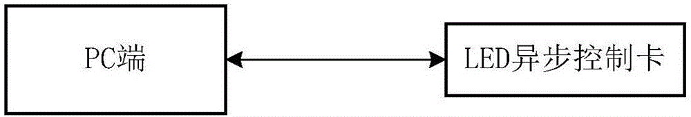
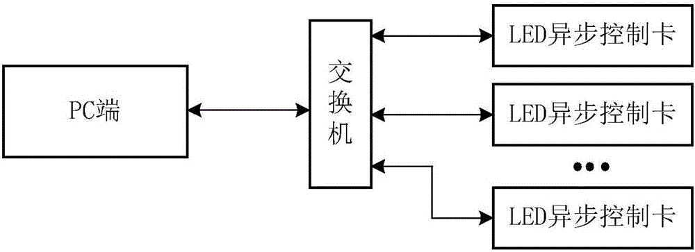
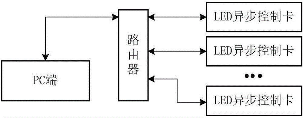
[0030] Generally speaking, in reality, the basic network construction environment of the LED control system that users usually encounter is as follows: 1) The PC is directly connected to the LED asynchronous control card, such as figure 1 2) The PC is connected to the LED asynchronous control card through a switch, such as figure 2 3) The PC is connected to the LED asynchronous control card through a router, such as image 3 as shown; and 4) the PC end is connected to the LED asynchronous control card through a router and a switch, such as Figure 4 shown. Of course, the actual network environment is far more than the four mentioned above, but the above four basically cover the basic conne...


PUM


Abstract

The present invention provides a network IP address automatic distribution method. The method comprises the steps: an upper computer initiates the UDP broadcast search connection; the upper computer establishes an IP address maintenance list according to the feedback information including a local IP address replied by an embedded device located in the same local area network; the upper computer randomly distributes one IP address with the same network segment with the upper computer for a target embedded device and determines whether the distributed IP address is available through a PING command or not; and when distributed IP address is available, recording the distributed IP address to the IP address maintenance list and issuing the distributed IP address to the target embedded device to allow the target embedded device to set the distributed IP address as the local IP address and initiate the TCP/IP connection after going into effect. The network IP address automatic distribution method can improve the reliability of the network connection of an embedded device such as a LED asynchronous control card and can overcome the offline problem that there is the IP distribution conflict for users caused by simultaneous connection of multiple terminal devices.

Description

technical field [0001] The invention relates to the field of network technology, in particular to a method for automatically assigning network IP addresses suitable for embedded devices. Background technique [0002] At present, most of the LED asynchronous control cards communicate with the PC through the network, and the network IP addresses of most LED asynchronous control cards are either automatically assigned from the router or set by the software system itself. Static IP address, or a static IP address set by the user. In practical applications, it is possible to encounter a network environment without a router or with a router but the DHCP service is turned off. For example, when a PC is connected to multiple LED asynchronous control cards and other devices with network IP addresses through a switch, in this case Under the system, if you want to achieve normal network connection and communication and hope that the device can set an available IP address by itself wit...

Claims


Application Information

Patent Timeline
Patent Type & Authority Applications(China)
IPC IPC(8): H04L29/12
CPCH04L61/5007H04L61/5038H04L61/5046H04L61/5092
Inventor 何琳琳刘延
Owner XIAN NOVASTAR TECH
Why Eureka
Try Eureka