Plant planting rack

A planting rack and plant technology, applied in the field of plant planting racks, can solve the problems of inability to reuse, waste of items, low space utilization rate, etc., and achieve the effects of saving people's time, long service life and simple structure

Inactive Publication Date: 2017-03-22
李尚苏
View PDF5 Cites 8 Cited by
  • Summary
  • Abstract
  • Description
  • Claims
  • Application Information

AI Technical Summary

Problems solved by technology

[0002] At present, many families use balconies to plant flowers, vegetables, etc., but generally use a single flower pot for planting, which has low space utilization. It is sintered, and the structure itself is dense and airtight. Usually, there are small holes at the bottom of the container to ensure air permeability. However, when watering, the water poured into the potted plants will seep out from the air holes quickly, polluting the environment, and will also cause long-term pollution. Corrosion damages the decorative frame and cannot be reused, resulting in waste of items
At the same time, when people raise potted flowers, they are often busy and neglect the daily irrigation management of potted flowers, because the specific time of watering flowers every day is different in spring, summer, autumn and winter. Generally speaking, in spring, autumn and winter, Around 10:00 in the morning and after 4:00 in the afternoon are suitable times for watering flowers and irrigation. At noon in midsummer, the temperature is high, and the transpiration of plants is strong, so it is not suitable for watering, otherwise the plants will be physiologically dry until they wither. Generally choose around 7 o'clock in the morning and after 5 o'clock in the afternoon. The choice of watering time is not satisfactory for people's fast-paced life now.

Method used


Image

  • Plant planting rack

Examples


Embodiment Construction

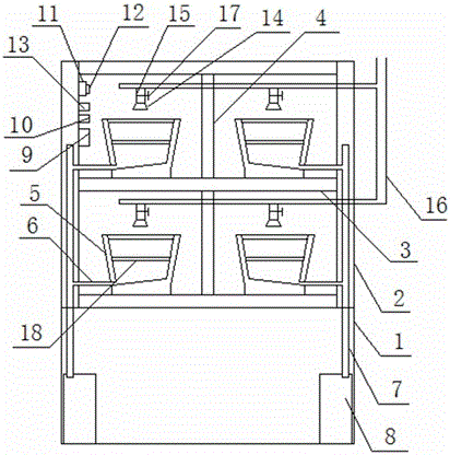
[0011] Such as figure 1 A plant planting stand shown includes a cabinet body 1, a hollow vertical board 2 and a cross brace 3, and the edges of both sides of the top of the cabinet body 1 are respectively fixed with hollow vertical boards 2, between the top and the bottom of the two hollow vertical boards 2 At least two cross braces 3 are fixedly installed, a vertical partition 4 is installed between two adjacent cross braces 3, a potted plant placement box 5 is arranged on the cross brace 3 between the vertical partition 4 and the hollow vertical plate 2, The bottom of the side wall of the potted plant placement box 5 is communicated with the hollow vertical plate 2 through the pipeline 6, the bottom of the hollow vertical plate 2 is communicated with the cabinet body 1, and the hollow vertical plate 2 is provided with a water pipe 7, and the upper end of the water pipe 7 is communicated with the pipeline 6, and the water pipe 7 The lower end is arranged in the cabinet body 1...


PUM


Abstract

The invention discloses a plant planting rack. The rack comprises a cabinet, hollow vertical plates and cross supports. The two side edges of the top of the cabinet are fixedly provided with the hollow vertical plates respectively, at least two cross supports are fixedly arranged between the tops and the bottoms of the two hollow vertical plates, vertical partition plates are arranged between the two adjacent cross supports, and potting placement boxes are arranged on the positions, between the vertical partition plates and the hollow vertical plates, of the cross supports, the bottoms of the side walls of the potting placement boxes are communicated with the hollow vertical plates through pipelines, hollow vertical plates are internally provided with water pipes, and the tops of the water pipes are communicated with the pipelines. A nozzle is arranged above each potting placement box, the nozzles are connected with a water inlet pipe through spraying pipes, electromagnetic valves are arranged on the water inlet pipe and electrically connected with a single chip control module through electromagnetic valve driving circuit modules, and the single chip control module is electrically connected with a clock module, a power supply module and a key display module respectively. The plant planting rack is simple in structure and long in service life and can be recycled, pot flowers can be moderately irrigated in time, and time can be saved for people.

Description

technical field [0001] The invention relates to the technical field of plant planting equipment, in particular to a plant planting stand. Background technique [0002] At present, many families use balconies to plant flowers, vegetables, etc., but generally use a single flower pot for planting, which has low space utilization. It is sintered, and the structure itself is dense and airtight. Usually, there are small holes at the bottom of the container to ensure air permeability. However, when watering, the water poured into the potted plants will seep out from the air holes quickly, polluting the environment, and will also cause long-term pollution. Corrosion damages the decorative frame and cannot be reused, resulting in waste of items. At the same time, when people raise potted flowers, they are often busy and neglect the daily irrigation management of potted flowers, because the specific time of watering flowers every day is different in spring, summer, autumn and winter....

Claims


Application Information

Patent Timeline
Patent Type & Authority Applications(China)
IPC IPC(8): A01G9/02A01G27/00A01G27/02
CPCA01G9/023A01G27/003A01G27/02
Inventor 李尚苏
Owner 李尚苏
Why Eureka
Try Eureka