Industrial paint spraying equipment for surface of steel pipe

A painting equipment and industrial technology, which is applied in the field of industrial steel pipe surface painting equipment, can solve the problems of incomplete painting, worker injury, time-consuming and labor-intensive manual painting, etc.

Active Publication Date: 2017-03-22
江苏新大高空工程有限公司
View PDF7 Cites 15 Cited by
  • Summary
  • Abstract
  • Description
  • Claims
  • Application Information

AI Technical Summary

Problems solved by technology

[0008] In order to overcome the disadvantages of incomplete spraying, time-consuming and labor-intensive manual spraying, and harm to workers caused by manual spraying, the technical problem to be solved by the present invention is to provide equipment with relatively comprehensive spraying, fast spraying speed, and An industrial steel pipe surface painting equipment with less injury to workers

Method used


Image

  • Industrial paint spraying equipment for surface of steel pipe
  • Industrial paint spraying equipment for surface of steel pipe
  • Industrial paint spraying equipment for surface of steel pipe

Examples


Embodiment 1

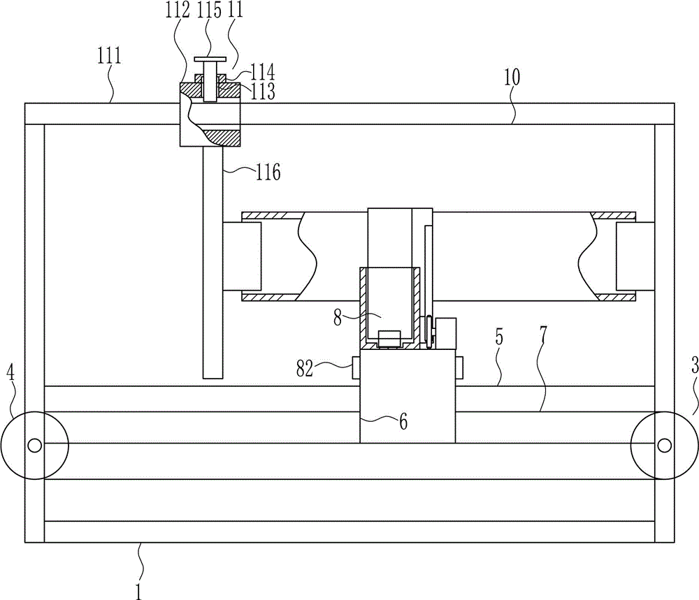
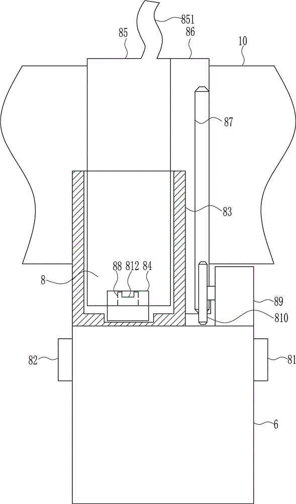
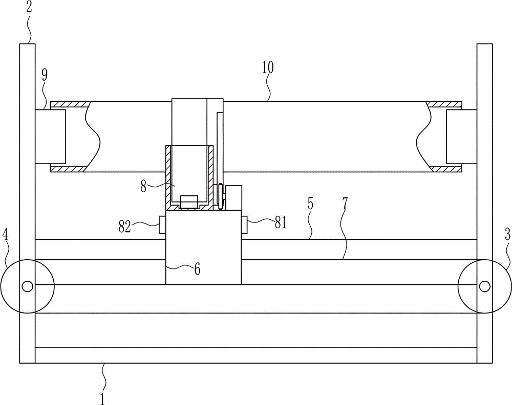
[0036] A kind of industrial steel pipe surface painting equipment, such as Figure 1-5 As shown, it includes a bottom plate 1, a support plate 2, a driving wheel 3, a driven wheel 4, a first slide rail 5, a first slider 6, a transmission bar 7, a painting device 8, a first fixed block 9 and a steel pipe 10, and the bottom plate 1 The left and right ends are symmetrically installed with support plates 2 by means of welding, the lower front side of the right support plate 2 is rotatably connected to the driving wheel 3, and the lower front side of the left support plate 2 is rotatably connected to the driven wheel 4, and the left and right sides A first slide rail 5 is connected between the support plates 2 by welding, and a first slide block 6 is slidably connected to the first slide rail 5, and a transmission strip 7 is wound around the driving wheel 3 and the driven wheel 4, and the transmission strip 7 One end of the upper side is connected to the right end of the slider, an...

Embodiment 2

[0038] A kind of industrial steel pipe surface painting equipment, such as Figure 1-5 As shown, it includes a bottom plate 1, a support plate 2, a driving wheel 3, a driven wheel 4, a first slide rail 5, a first slider 6, a transmission bar 7, a painting device 8, a first fixed block 9 and a steel pipe 10, and the bottom plate 1 The left and right ends are symmetrically installed with support plates 2 by means of welding, the lower front side of the right support plate 2 is rotatably connected to the driving wheel 3, and the lower front side of the left support plate 2 is rotatably connected to the driven wheel 4, and the left and right sides A first slide rail 5 is connected between the support plates 2 by welding, and a first slide block 6 is slidably connected to the first slide rail 5, and a transmission strip 7 is wound around the driving wheel 3 and the driven wheel 4, and the transmission strip 7 One end of the upper side is connected to the right end of the slider, an...

Embodiment 3

[0041] A kind of industrial steel pipe surface painting equipment, such as Figure 1-5 As shown, it includes a bottom plate 1, a support plate 2, a driving wheel 3, a driven wheel 4, a first slide rail 5, a first slider 6, a transmission bar 7, a painting device 8, a first fixed block 9 and a steel pipe 10, and the bottom plate 1 The left and right ends are symmetrically installed with support plates 2 by means of welding, the lower front side of the right support plate 2 is rotatably connected to the driving wheel 3, and the lower front side of the left support plate 2 is rotatably connected to the driven wheel 4, and the left and right sides A first slide rail 5 is connected between the support plates 2 by welding, and a first slide block 6 is slidably connected to the first slide rail 5, and a transmission strip 7 is wound around the driving wheel 3 and the driven wheel 4, and the transmission strip 7 One end of the upper side is connected to the right end of the slider, an...


PUM


Abstract

The invention relates to paint spraying equipment, in particular to industrial paint spraying equipment for the surface of a steel pipe. According to the industrial paint spraying equipment for the surface of the steel pipe, paint spraying is comprehensive, the paint spraying speed is high, and harm to workers in the paint spraying process is small. The industrial paint spraying equipment for the surface of the steel pipe comprises a base plate, supporting plates, a driving wheel, a driven wheel, a first sliding rail, a first sliding block and the like. The supporting plates are symmetrically mounted at the left end and the right end of the base plate in a welded mode. The driving wheel is rotatably connected to the front side of the lower portion of the supporting plate on the right side. The driven wheel is rotatably connected to the front side of the lower portion of the left supporting plate. The first sliding rail is connected between the supporting plates on the left side and the right side in a welded mode. By adoption of the paint spraying equipment, the effects of comprehensive paint spraying, high paint spraying speed, and little harm to the workers in the paint spraying process are achieved.

Description

technical field [0001] The invention relates to a paint spraying device, in particular to a paint spraying device for the surface of an industrial steel pipe. Background technique [0002] The development of steel pipe production technology began with the rise of the bicycle manufacturing industry, the development of petroleum in the early 19th century, the manufacture of ships, boilers, and aircraft during the two world wars, the manufacture of thermal power boilers after the Second World War, the development of the chemical industry and Drilling, production and transportation of oil and natural gas have strongly promoted the development of steel pipe industry in terms of variety, output and quality. [0003] The steel pipe is used to transfer fluid and powder, exchange heat and produce mechanical parts and containers, what's more it's a kind of economical steel. Using steel pipes to manufacture building structure grids, pillars and mechanical supports can reduce weight an...

Claims


Application Information

Patent Timeline
Patent Type & Authority Applications(China)
IPC IPC(8): B05B13/02B05B13/04
CPCB05B13/0207B05B13/0463
Inventor 不公告发明人
Owner 江苏新大高空工程有限公司
Why Eureka
Try Eureka