
Temporary speed limiting method based on a plurality of in-place working stations and DSU (Database Storage Unit)

A technology of temporary speed limit and workstation, which is applied in the fields of railway car body parts, railway signal and safety, transportation center control system, etc. It can solve the problem of low intelligence, inability of DSU to issue temporary speed limit commands, lack of automatic speed limit transmission and Automatic control measures and other issues to achieve the effect of ensuring safety

Active Publication Date: 2017-03-22
TRAFFIC CONTROL TECH CO LTD
View PDF7 Cites 7 Cited by
  • Summary
  • Abstract
  • Description
  • Claims
  • Application Information

AI Technical Summary

Problems solved by technology

At present, my country's intelligence in the field of train control is low and there is too much manual intervention, especially in the temporary speed limit section of the blind spot of train control. Drivers only use temporary speed limit signs on the ground to identify information, and there is a lack of automatic speed limit transmission and automatic control measures. , with the increase of train speed and density, higher requirements are placed on the safety and automation of the entire train control system while operating efficiently
[0003] The traditional temporary speed limit scheme is only aimed at a single on-site workstation, that is, an on-site workstation can only issue a temporary speed limit command to its DSU (Database Storage Unit), and other on-site workstations cannot The DSU issued a temporary speed limit order

Method used


Image

  • Temporary speed limiting method based on a plurality of in-place working stations and DSU (Database Storage Unit)
  • Temporary speed limiting method based on a plurality of in-place working stations and DSU (Database Storage Unit)
  • Temporary speed limiting method based on a plurality of in-place working stations and DSU (Database Storage Unit)

Examples


Embodiment Construction

[0040] In order to make the purpose, technical solutions and advantages of the embodiments of the present invention clearer, the technical solutions in the embodiments of the present invention will be clearly described below in conjunction with the accompanying drawings in the embodiments of the present invention. Obviously, the described embodiments are the Some, but not all, embodiments are invented.

[0041] In the embodiment of the present invention, in order to adapt to the temporary speed limit setting of the DSU issued by the multi-site workstations, the present invention provides a temporary speed limit method based on the multi-site workstations, so that all the multi-site workstations can set the temporary speed limit, While operating efficiently, the safety and automation of the entire train control system have been better improved.

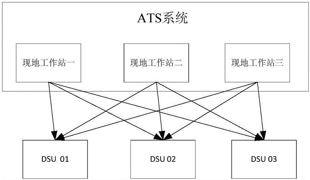
[0042] figure 1 It shows a schematic diagram of the interaction between the on-site workstation and the DSU provided by an embodimen...


PUM


Abstract

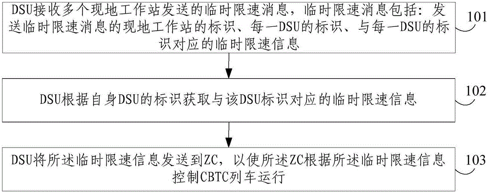
The invention discloses a temporary speed limiting method based on a plurality of in-place working stations and a DSU (Database Storage Unit). The temporary speed limiting method comprises the following steps that: the DSU receives temporary speed limiting messages transmitted by the plurality of in-place working stations, the DSU and the plurality of in-place working stations belong to the same ATS (Automatic Train Supervision) system; the DSU acquires the temporary speed limiting information corresponding to the identifier of the DSU according to the identifier of the DSU; and the temporary speed limiting information is transmitted to a ZC (Zone Controller) so that the ZC controls a CBTC (Communication Based Train Control) train to run according to the temporary speed limiting information, wherein the temporary speed limiting messages comprise identifiers of the in-place working stations, which transmit the temporary speed limiting messages, and also comprise an identifier of each DSU and temporary speed limiting information corresponding to the identifier of each DSU. According to the invention, the temporary speed limiting information of the plurality of in-place working stations are received through the DSU so as to ensure the safety, stability and fault tolerance of a train control system in the CBTC running mode.

Description

technical field [0001] The invention relates to the field of signal control, in particular to a temporary speed limiting method based on a multi-site workstation and a DSU. Background technique [0002] With the continuous development of urban rail transit, the communication-based CBTC (Communication Based Train Control) has brought great changes to the signal system of urban rail transit, and the safe operation of trains is becoming more and more important. At present, my country's intelligence in the field of train control is low and there is too much manual intervention, especially in the temporary speed limit section of the blind spot of train control. Drivers only use temporary speed limit signs on the ground to identify information, and there is a lack of automatic speed limit transmission and automatic control measures. , with the increase of train speed and density, higher requirements are put forward for the safety and automation of the entire train control system wh...

Claims


Application Information

Patent Timeline
IPC IPC(8): B61L27/00
CPCB61L2027/204B61L27/20
Inventor 张强杜恒
Owner TRAFFIC CONTROL TECH CO LTD
Learn More