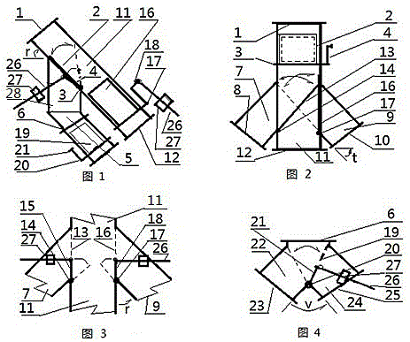
[0051] The present invention will be further described below in conjunction with the drawings and specific embodiments.
[0052] The conversion method of five silos for unloading of one hoist, including: feeding port of unloading converter 1, opening and closing door A 2, door shaft A 3, door shaft arm 4, attached feed pipe 5 , Attached material pipe flange 6, main material pipe left pant pipe 7, No. 1 silo cut pipe flange 8, main material pipe right pant pipe 9, No. 3 silo cut pipe flange 10, main Feeding pipe 11, No. 2 silo feed pipe flange 12, No. B opening door 13, No. B door shaft 14, No. B door shaft arm 15, C No. opening door 16, C No. door shaft 17, C Door shaft arm 18, No. D conversion door 19, No. D door shaft 20, No. D door shaft arm 21, with a lower tube left pants tube 22, No. 4 silo lower tube flange 23, with a lower tube Right pants tube 24, No. 5 silo lower feed pipe flange 25, electric screw 26, screw motor 27, attached lower feed pipe connecting pipe 28.
[0053] The feed inlet 1 of the feeding converter is connected with the feeding inlet of the hoist.
[0054] The feed inlet 1 of the blanking converter is downward to the main blanking pipe 11.
[0055] The outlet of the main feeding pipe 11 is the feeding pipe flange 12 of the No. 2 silo, which is connected with the feeding pipe of the No. 2 silo.
[0056] The left trousers branch pipe of the main cutting pipe is the main cutting pipe and the left trousers pipe 7, and the outlet is the No. 1 silo lowering pipe flange 8, which is connected with the No. 1 silo feeding pipe.
[0057] The right trousers branch pipe of the main cutting pipe is the main cutting pipe, the right trousers pipe 9, and the outlet is the No. 3 silo cutting pipe flange 10, which is connected with the No. 3 silo feeding pipe.
[0058] Below the main feeding pipe inlet 1 is provided with a No. A switch door 2 attached to the feeding pipe 5, and the attached feeding pipe connecting pipe 28 connects the main feeding pipe 11 and the attached feeding pipe 5 into one body.
[0059] The attached feed tube 5 with the outlet of the attached feed tube flange 6 is provided with a left pant tube 22 with a feed tube and a right pant tube 24 with a feed tube.
[0060] The exit of the left pant tube 22 with the attached feed tube is the feed pipe flange 23 of the No. 4 silo, and the outlet is connected with the feed pipe of the No. 4 silo.
[0061] The outlet of the right pants tube 24 with the attached feed tube is the flange 25 of the No. 5 silo lower feed pipe, and the outlet is connected with the No. 5 silo feed pipe.
[0062] The feeding method of No. 2 silo.
[0063] Step 1: The electric screw 26 is driven by the screw motor 27 to move linearly, pushing the door shaft arm 4 of the No. A to rotate the No. A door shaft 3, and driving the No. A switch door 2 to close the attached feed pipe 5 and open the main feed pipe 11.
[0064] Step 2: The screw motor 27 drives the electric screw 26 to move linearly, pushes the door shaft arm 15 of No. B, makes the No. B door shaft 14 rotate, drives the No. B switch door 13, opens the main feeding pipe 11, and closes the main feeding Tube left pants tube 7.
[0065] Step 3: The screw motor 27 drives the electric screw 26 to move linearly, pushes the C door shaft arm 18, causes the C door shaft 17 to rotate, drives the C opening and closing door 16, opens the main feed pipe 11, and closes the main feed Tube right pants tube 9.
[0066] Step 4: The switch door 2 of A is closed, the switch door 13 of B is closed, and the switch door 16 of C is closed. The main feeding pipe 11 passes through the feeding pipe flange 12 of the No. 2 silo and discharges to the No. 2 silo.
[0067] The feeding method of No. 1 silo.
[0068] Step 1: The electric screw 26 is driven by the screw motor 27 to move linearly, pushing the door shaft arm 4 of the No. A to rotate the No. A door shaft 3, and driving the No. A switch door 2 to close the attached feed pipe 5 and open the main feed pipe 11.
[0069] Step 2: The screw motor 27 drives the electric screw 26 to move linearly, pushes the door shaft arm 15 of No. B, makes the No. B door shaft 14 rotate, drives the No. B switch door 13, closes the main feed pipe 11, and opens the main lower The left pant tube 7 of the feed pipe passes through the flange 8 of the feed pipe of the No. 1 silo to start feeding to the No. 1 silo; at this time: the No. A switch door is closed, and the No. C switch door is closed.
[0070] The feeding method of No. 3 silo.
[0071] Step 1: The electric screw 26 is driven by the screw motor 27 to move linearly, pushing the door shaft arm 4 of the No. A to rotate the No. A door shaft 3, and driving the No. A switch door 2 to close the attached feed pipe 5 and open the main feed pipe 11.
[0072] Step 2: The screw motor 27 drives the electric screw 26 to move linearly, pushes the C door shaft arm 18, makes the C door shaft 17 rotate, drives the C switch door 16 to close the main feeding pipe 11 and open the main feeding pipe The right pant tube 9 passes through the feeding pipe flange 10 of the No. 3 silo and begins to discharge to the No. 3 silo; at this time: the No. A switch door is closed, and the No. B switch door is closed.
[0073] The feeding method of No. 4 silo.
[0074] Step 1: The screw motor 27 drives the electric screw 26 to move linearly, pushes the door shaft arm 4 of the A door, makes the door shaft 3 rotate, drives the door A to open, and close the main discharge pipe 11 at the same time.
[0075] Step 2: The screw motor 27 drives the electric screw 26 to move linearly, pushes the D door shaft arm 18, makes the D door shaft 17 rotate, and drives the D conversion door 19 to close the right pants tube 24 with the feed tube and open at the same time The left pant tube 22 is attached to the feed tube, and the feed tube flange 23 of the No. 4 silo begins to discharge to the No. 4 silo.
[0076] The feeding method of No. 5 silo.
[0077] Step 1: The screw motor 27 drives the electric screw 26 to move linearly, pushes the door shaft arm 4 of the A door, makes the door shaft 3 rotate, drives the door A to open, and close the main discharge pipe 11 at the same time.
[0078] Step 2: The screw motor 27 drives the electric screw 26 to move linearly, pushes the D door shaft arm 18, makes the D door shaft 17 rotate, and drives the D conversion door 19 to close the left pants tube 22 with the feed tube and open at the same time Attach the right pant tube 24 of the feed tube, and pass through the flange 25 of the feed tube of the No. 5 silo to start feeding to the No. 5 silo.
[0079] The angle between the center line of the main feed pipe 11 and the attached feed pipe 5 and the horizontal line is r, r=45 0 -50 0 degree.
[0080] The angle between the center line of the left pant tube 7 of the main cutting tube and the center line of the right pant tube 9 of the main cutting tube and the center line of the main cutting tube 11 is t, t=40 0 -45 0 degree.
[0081] The bottom planes of the main cutting tube 11, the main cutting tube left pant tube 7, and the main cutting tube right pant tube 9 are required to be on the same plane.
[0082] The center line of the connecting pipe 28 between the attached feed pipe 5 and the main feed pipe 11 is a vertical line.
[0083] The angle V between the center line of the left pant tube 22 with the lower feed tube and the right pant tube 24 with the lower feed tube is 80 0 -90 0 degree.
[0084] The main cutting tube 11, the main cutting tube left pant tube 7, the main cutting tube right pant tube 9, the attached cutting tube 5, the left pant tube 22 with the cutting tube and the right panty tube 24 with the cutting tube are rectangular. Or square tube.
[0085] Each screw motor 27 is controlled by an integrated electric control box.