Part tray lifter

A technology for lifting pallets and parts, which is applied to conveyors, mechanical conveyors, rollers, etc., and can solve problems that affect production beats, poor safety, and low efficiency

Inactive Publication Date: 2017-03-22
WUXI MINGZHU STEEL BALL
View PDF12 Cites 8 Cited by
  • Summary
  • Abstract
  • Description
  • Claims
  • Application Information

AI Technical Summary

Problems solved by technology

[0002] The parts pallet transported from the parts assembly line needs to be transferred to the next process. The working position of the tooling in this process is often at a diff

Method used


Image

  • Part tray lifter
  • Part tray lifter
  • Part tray lifter

Examples


Embodiment Construction

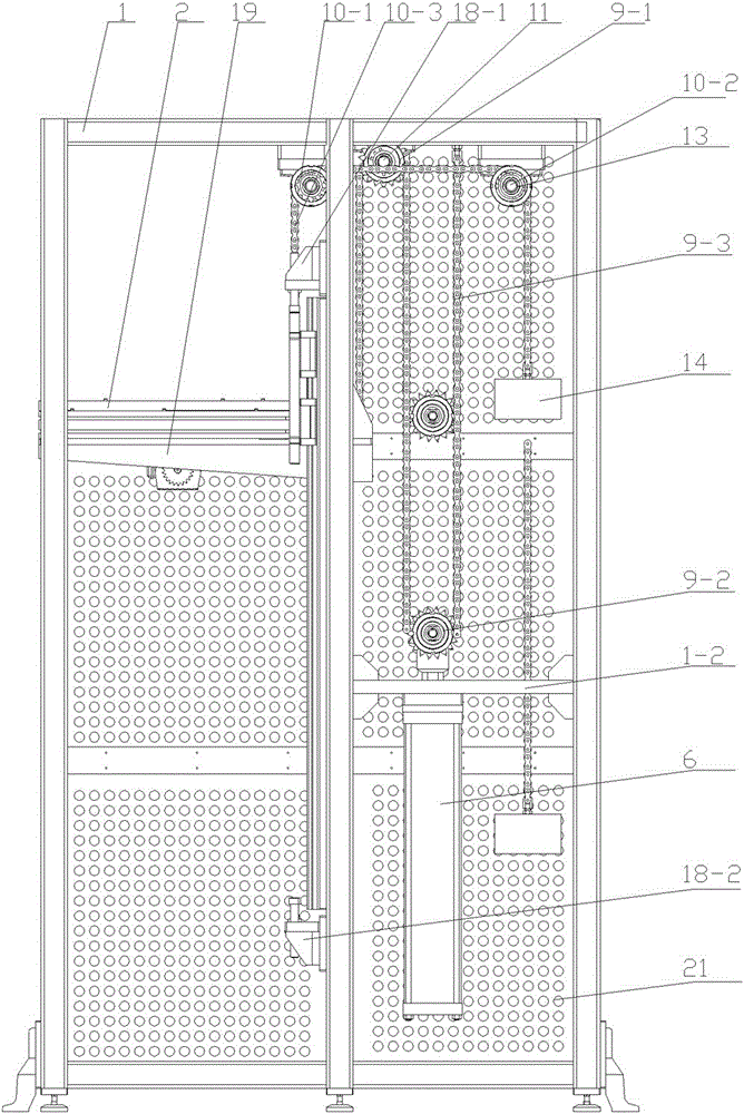
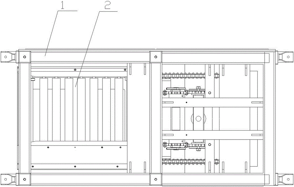
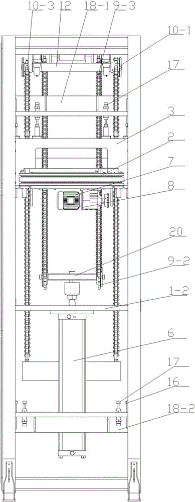
[0025] figure 1 , figure 2 , image 3 , Figure 4 Middle: frame 1, support frame 1-1, support plate 1-2; roller conveying seat 2, roller 2-1, inclined guide plate 2-2; lifting seat 3; guide rail 4; slider 5; cylinder 6; transmission Motor 7; mounting frame 8; first chain structure 9, first sprocket wheel 9-1, second sprocket wheel 9-2, first chain 9-3; second chain structure 10, third sprocket wheel 10-1, Fourth sprocket 10-2, second chain 10-3; first connecting shaft 11, second connecting shaft 12, third connecting shaft 13; counterweight 14; sleeve 15; limit post 16, buffer limit Column 17; upper limit installation plate 18-1, lower limit installation plate 18-2; fixed plate 19; connecting plate 20; protective plate 21.

[0026] See Figure 1-Figure 4 As shown, a parts tray hoist includes a frame 1, a roller conveying seat 2, and rollers 2-1 are arranged on the roller conveying seat 2, and a plurality of parallel rollers 2-1 arranged side by side pass through sprockets...


PUM


Abstract

The invention provides a part tray lifer which can be suitable for a part assembly line, can realizably realize automatically transferring part trays from the part assembly line to next tool equipment at working height different from that of the part assembly line. The part tray lifter comprises a rack and a roller conveying base, wherein rollers are arranged on the roller conveying base, are connected through chain wheels, and are driven by a transmission motor. The part tray lifter is characterized by further comprising a lifting base, an air cylinder, a first chain structure, a second chain structure and a limiting structure, wherein the lifting base is mounted on the rack through a guide rail in a sliding mode; the roller conveying base is connected to the lifting base; one end of the first chain structure is connected with the lifting base, and the other end of the first chain structure is connected with the air cylinder, and then is mounted on the top of the rack; one end of the second chain structure is connected with the lifting base, and the other end of the second chain structure is connected with a counterweight block; the limiting structure is equipped with the rack; the limiting structure comprises a limiting post; an induction switch is further mounted on the lifting base; and the induction switch is connected with a transmission motor in an electrically-controlled mode.

Description

technical field [0001] The invention relates to the technical field of conveying assembly parts, in particular to a part pallet lifter. Background technique [0002] The parts trays conveyed from the parts assembly line need to be transferred to the next process. The working position of the tooling in this process is often at a different working height from the parts assembly line. In the prior art, it is common to rely on manual handling, which is inefficient and affects the production cycle. , poor security. Contents of the invention [0003] In order to solve the problems of the prior art, the present invention provides a parts tray hoist, which can be adapted to the parts assembly line, and can reliably realize the automatic transfer of the parts tray from the parts assembly line to the next tooling that is at a different working height from the parts assembly line. equipment. [0004] Its technical solution is as follows: it includes a frame, a roller conveying seat...

Claims


Application Information

Patent Timeline
IPC IPC(8): B65G37/00B65G17/32B65G13/00
CPCB65G37/00B65G13/00B65G17/32
Inventor 吴昊
Owner WUXI MINGZHU STEEL BALL
Why Eureka
Try Eureka