90-degree overturning airflow pneumatic conveying line

A technology of air flow and air delivery, which is applied in the field of 90° reverse air flow and air delivery line, which can solve the problems of large friction at the bottom of the tank, long production period, and high cost, and achieve the effects of short production period, low cost and reduced friction

Inactive Publication Date: 2017-03-22
北京鑫顺盛源科技有限公司
View PDF6 Cites 0 Cited by
  • Summary
  • Abstract
  • Description
  • Claims
  • Application Information

AI Technical Summary

Problems solved by technology

[0003] In the prior art, 90° turning equipment is used, which has high cost, long production period, and large friction on the bottom of the tank

Method used


Image

  • 90-degree overturning airflow pneumatic conveying line
  • 90-degree overturning airflow pneumatic conveying line
  • 90-degree overturning airflow pneumatic conveying line

Examples


specific Embodiment approach

[0018] The preferred embodiment of the 90° overturned air flow air delivery line of the present invention is:

[0019] It includes a blowing board, a U-shaped box and a fan. The U-shaped box is a cavity with an open upper end and a sealed lower end. There is a wind shield in the middle of the U-shaped box. The opening of the U-shaped box faces upwards. The blowing plate is installed at the opening of the U-shaped box so that the U-shaped box forms a pressurized cavity, the pressurized cavity is connected with the fan, and the surface of the blowing plate is opened along the conveying direction. There are a plurality of directional blowing ports, and the multiple directional blowing ports form an air channel flowing in the conveying direction, and the wind source provided by the fan creates pressure in the pressurized cavity to make the airflow flow out from the directional blowing ports in the conveying direction.

[0020] The U-shaped box includes an upper bellows U-shaped bo...

specific Embodiment

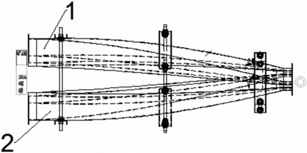
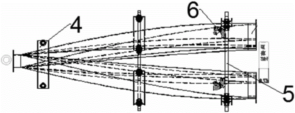
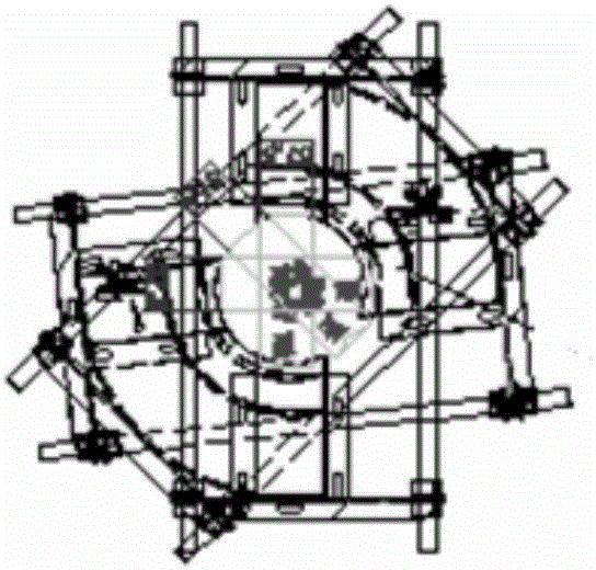
[0026] Such as Figure 1 to Figure 7 As shown, it includes upper and lower bellows. The air blowing plate is 304 mirror stainless steel. The stainless steel retaining strip and polymer wear-resistant strip are used as the guide rails of the cans to quickly transport the cans to the corresponding equipment inlets. The upper and lower bellows and wind plates rotate 90°; The side polymer wear-resistant strips can be interchanged according to the different outer diameter tanks produced, and the 90° flip air blower is a shaped product, which can be adjusted slightly (±5mm). The air blowing plate is made of 304 mirror stainless steel, and the directional blowing port is Disconnected on three sides. The ventilation fan is used as the air source to reach a certain pressure value range, and then flows in the same direction through the special directional blower port, thereby driving the cans between the upper bellows box and the lower bellows box to run and transport, achieving the pur...


PUM


Abstract

The invention discloses a 90-degree overturning airflow pneumatic conveying line. The 90-degree overturning airflow pneumatic conveying line comprises a blowing plate, U-shaped boxes and a fan. Each U-shaped box is a cavity with the upper end open and the lower end sealed; an air partition plate is arranged in the middle of each U-shaped box; and an opening of each U-shaped box faces upwards. The blowing plate is mounted at the openings of the U-shaped boxes so that the U-shaped boxes can form pressurizing cavities. The pressurizing cavities are connected with the fan. A plurality of directional blowing ports are formed in the surface of the blowing plate in the conveying direction. The multiple directional blowing ports form an air channel flowing in the conveying direction. Pressure is formed in the pressurizing cavity through an air source provided by the fan pressure so that airflow can flow out through the directional blowing ports in the conveying direction. The U-shaped box and the blowing plate are provided with 90-degree rotation devices. The blowing plate is made form 304 mirror finished stainless steel. Stainless steel barrier strips and macromolecular abrasion-resistant strips are arranged on the surface of the blowing plate to be used as guide rails of ring-pull cans. After the directional blowing ports are disconnected, the directional blowing ports are bent downwards by a certain angle. The 90-degree overturning airflow pneumatic conveying line can reach 2000-3000 CMP, the cost is low, the production period is short, and friction to can bottoms is reduced.

Description

technical field [0001] The invention relates to a production equipment for pop cans, in particular to a 90° overturn air flow air feeding line. Background technique [0002] In the production of cans, there is a link of entering the necking and flanging machine. The cans are conveyed horizontally and upwards from the mouth of the ground. Usually, the cans of the necking and flanging machine equipment are perpendicular to the cans. Before the cans enter the necking and flanging machine, they need to pass through 90 °turning equipment to complete, to meet the relationship with the entrance, the necking and flanging machine outlet also needs to convert the cans through the 90°turning equipment to the can bottom contacting the conveyor belt, so that the subsequent transportation is convenient, fast and reasonable. The can 90° airflow flip air delivery line is usually used in the inlet and outlet of the necking and flanging machine. [0003] In the prior art, 90° turning equipme...

Claims


Application Information

Patent Timeline
Patent Type & Authority Applications(China)
IPC IPC(8): B65G47/248
CPCB65G47/248B65G2201/0252
Inventor 张俊龙张玉喜钟相武孙晓利
Owner 北京鑫顺盛源科技有限公司
Why Eureka
Try Eureka