C type retaining ring feeding device

A C-type buckle and buckle technology, which is applied in the direction of conveyor objects, transportation and packaging, can solve problems such as low work efficiency, and achieve the effect of improving work efficiency, reducing production costs, and realizing mechanical automation.

Active Publication Date: 2017-03-22
李帅
View PDF7 Cites 9 Cited by
  • Summary
  • Abstract
  • Description
  • Claims
  • Application Information

AI Technical Summary

Problems solved by technology

[0002] The clasp, also known as the snap ring or retaining ring, is a kind of fastener, which is installed in the shaft groove or hole groove of the machine and equipment, and plays the role of preventing the axial movement of the parts on the shaft or hole. In the prior art, the feeding of the C-shaped buckle is mainly done manually, which makes the work efficiency low. In view of this, it is necessary to improve the method of feeding the buckle

Method used


Image

  • C type retaining ring feeding device
  • C type retaining ring feeding device
  • C type retaining ring feeding device

Examples


Embodiment Construction

[0027] The preferred embodiments of the present invention will be described in detail below in conjunction with the accompanying drawings, so that the advantages and features of the invention can be more easily understood by those skilled in the art, so as to define the protection scope of the present invention more clearly.

[0028] see Figure 1 to Figure 17 , the embodiment of the present invention includes:

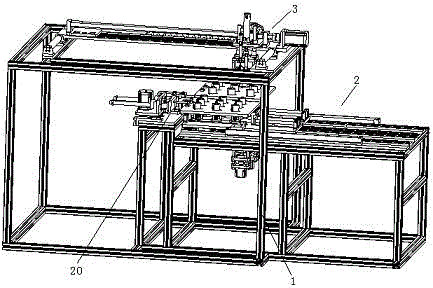
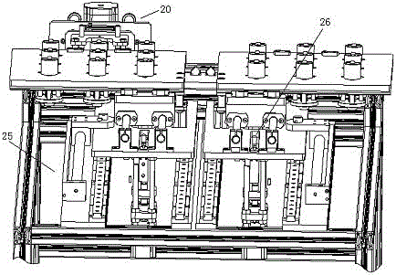
[0029] A C-shaped clasp feeding device, the C-shaped clasp feeding equipment includes a frame 1 installed on the ground, and the frame 1 is provided with a C-shaped clasp feeding mechanism 2 and a C-shaped clasp unloading mechanism 3. The C-shaped buckle feeding mechanism 3 is located above the C-shaped buckle feeding mechanism 2; the C-shaped buckle feeding mechanism 2 includes the pallet transposition device 20 on the frame 1 and the C-shaped buckle feeding mechanism Device 25, the C-shaped buckle feeding device 25 is located on one side of the pallet transposition...


PUM


Abstract

The invention discloses a C type retaining ring feeding device. The C type retaining ring feeding device comprises a rack installed on the ground; the rack is provided with a C type retaining ring supplying mechanism and a C type retaining ring discharging mechanism; the C type retaining ring discharging mechanism is located above the C type retaining ring supplying mechanism; the C type retaining ring supplying mechanism comprises a tray transposition device and a C type retaining ring supplying device which are arranged on the rack, and the C type retaining ring supplying device is located on one side of the tray transposition device; the tray transposition device comprises an installing plate fixed to the rack; the installing plate is provided with a tray displacement assembly and a positioning assembly; and the positioning assembly is arranged on the lower plane of the installing plate. Due to the above manner, the C type retaining ring feeding device can replace manual work to perform automatic feeding on C type retaining rings.

Description

technical field [0001] The invention relates to the field of mechanical automation, in particular to a C-shaped buckle feeding device. Background technique [0002] The clasp, also known as the snap ring or retaining ring, is a kind of fastener, which is installed in the shaft groove or hole groove of the machine and equipment, and plays the role of preventing the axial movement of the parts on the shaft or hole. In the prior art, the feeding of the C-shaped buckle is mainly done manually, which makes the work efficiency low. In view of this, it is necessary to improve the method of feeding the buckle. Contents of the invention [0003] The technical problem mainly solved by the present invention is to provide a C-shaped clasp feeding device, which has a simple structure and can automatically load the C-shaped clasp instead of manually. [0004] In order to solve the above technical problems, a technical solution adopted by the present invention is to provide a C-shaped...

Claims


Application Information

Patent Timeline
Patent Type & Authority Applications(China)
IPC IPC(8): B65G47/74B65G47/90
CPCB65G47/74B65G47/901
Inventor 赵玲玲
Owner 李帅
Why Eureka
Try Eureka