Building material forming mould box

A technology for mold boxes and building materials, which is applied in ceramic molding machines, ceramic molding cores, ceramic molding mandrels, etc., can solve the common problems of high labor intensity of manual operation of end mold demoulding, manual mold box labor, etc., and achieves low manufacturing cost. The effect of high yield

Pending Publication Date: 2017-12-19
胡云模
View PDF16 Cites 8 Cited by
  • Summary
  • Abstract
  • Description
  • Claims
  • Application Information

AI Technical Summary

Problems solved by technology

Currently used equipment and patents: 201210138956.9 Gypsum block forming machine, 201010229723.0 A gypsum block pouring automatic forming mold, 01251824.7 A lightweight wallboard machine, 98242136.2 Lightweight wallboard motorized vertical formwork, 02260859.1 Lightweight wallboard Machines, etc., the common common problem is that manual operation of end mold demoulding is labor-intensive
One is to take the end mold up and down manually, and the other is to connect the hinge under the end mold, and then open and close the end mold by hydraulic pressure or air pressure, but the locking of the mold box is still manual

Method used


Image

  • Building material forming mould box
  • Building material forming mould box

Examples


Embodiment 1

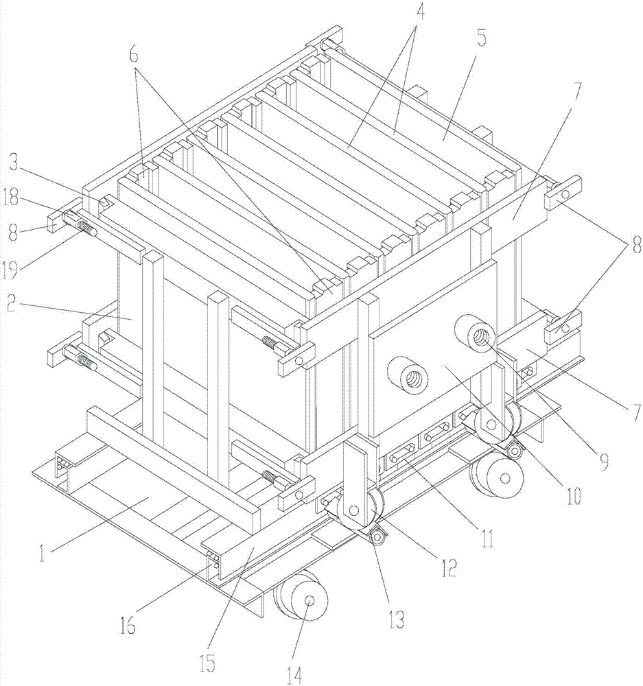
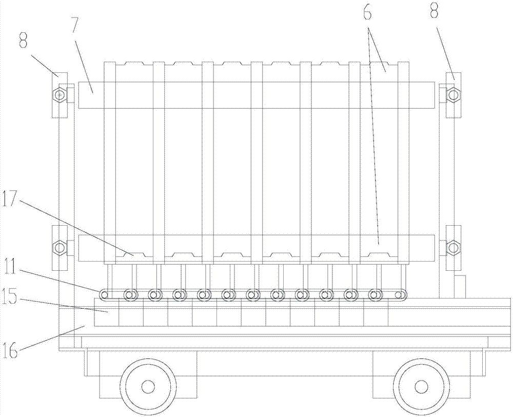
[0019] Example 1, such as figure 1 , 2 The building material molding mold box shown includes a mold box running on rails, and the chassis 1 of the mold box is provided with a front side formwork 2 and a rear side formwork 5 arranged in parallel to each other and arranged on the front side formwork 2 and the rear side. A plurality of partition molds 4 between the templates 5, the space between the front side template 2 and the rear side template 5 is divided into a plurality of mold cavities by the partition mold 4, and the left and right sides of the mold cavity are provided with end molds 6 (end molds 6 It consists of multiple pieces connected or a large block to seal several mold cavities), the bottom of the mold cavity is provided with a bottom mold 17; the chassis 1 is provided with front and rear guide rails 16 parallel to each other (the front and rear guide rails 16 have various shapes or structure), the front side template 2, the rear side template 5, the partition mo...

Embodiment 2

[0020] Embodiment 2, left and right guide rails 13 (the left and right guide rails 13 have various shapes or structures) are set on the underframe 1 in the described embodiment 1, the end module 7 is fixed on the end mold 6, and the pulley 12 (the pulley) is arranged below the end module 7. 12 rotate or do not rotate or other shapes or structures) slide back and forth on the left and right guide rails 13, and also drove the end die 6 to slide back and forth on the left and right guide rails 13 simultaneously, making the movement of the end die easy and accurate.

Embodiment 3

[0021] Embodiment 3, the end mold 6 and the bottom mold 17 in the above-mentioned embodiment 1 are provided with concave-convex tenons and tenon grooves, and the upper end of the end mold 6 is connected with the upper mold, so that there are concave-convex tenon and tenon grooves around the product produced .


PUM


Abstract

The invention discloses a building material forming mould box. The building material forming mould box comprises a mould box which operates on railways; a front side mould plate and a rear side mould plate which are oppositely arranged on an underframe of the mould box; the space between the front side mould plate and the rear side mould plate is divided into a plurality of mould cavities; end moulds are arranged on the left side and the right side of each mould cavity; a bottom mould is arranged at the bottom of each mould cavity; front-back guide rails and sliding pieces are also arranged on the underframe; the front side mould plate, the bottom mould, partition moulds, and the rear side mould plate are respectively connected with the sliding pieces; adjacent two sliding pieces are movably connected with each other; the rear side mould plate is fixed to the underframe; the end moulds can move horizontally; mechanical automation of mould opening and mould closing is realized through a locking mould of the mould box; and the building material forming mould box disclosed by the invention is applicable to automatic assembly line production of building products, such as bricks, blocks, plates and prefabricated parts.

Description

technical field [0001] The invention relates to the technical field of moulds, in particular to a mold box for forming building materials such as bricks, blocks, boards, and prefabricated components. Background technique [0002] Building materials are a general term for materials used in civil engineering and construction engineering. It can be divided into structural materials, decorative materials and some special materials. Blocks are artificial blocks for masonry. They are a new type of wall material. They are relatively commonly used structural materials with a large amount. There are also various special-shaped blocks. The block is an artificial block made of concrete or building gypsum as the main raw material, which is made by adding water, stirring, pouring and drying. The requirements of wall reform in the development of industrialization. Currently used equipment and patents: 201210138956.9 Gypsum block forming machine, 201010229723.0 A gypsum block pouring aut...

Claims


Application Information

Patent Timeline
Patent Type & Authority Applications(China)
IPC IPC(8): B28B7/24B28B7/16B28B7/00B28B7/28
CPCB28B7/0002B28B7/0014B28B7/162B28B7/164B28B7/241B28B7/245B28B7/28
Inventor 胡云模
Owner 胡云模
Why Eureka
Try Eureka