Novel feeder

A feeder, a new type of technology, is applied in the direction of large containers, conveyor objects, containers, etc., and can solve problems such as inability to feed materials, blockage of the cone bucket, inaccurate positioning of the working hopper and the cone bucket, etc., to achieve the solution of blockage and easy dredging Effect

Active Publication Date: 2017-03-22
新昌县云大农业有限公司
View PDF6 Cites 6 Cited by
  • Summary
  • Abstract
  • Description
  • Claims
  • Application Information

AI Technical Summary

Problems solved by technology

[0003] The current hopper lifting feeder manually moves the loaded working hopper to the bottom of the cone, and buckles the working hopper and the cone. Due to manual operation, it is impossible to accurately position the working hopper in the cone with the naked eye. It needs to be adjusted many times, which takes a long time and reduces work efficiency. At the same time, because a large amount of material flows out through the valve on the cone bucket at the same time, and the particle size and humidity of the material are different, it is extremely difficult. It is easy to cause the bottom of the cone to be blocked, and the feeding work cannot be carried out smoothly
[0004] Therefore, it is urgent to develop a new type of feeder that can accurately position the working hopper directly below the cone bucket and facilitate the dredging of the cone bucket to overcome the inaccurate positioning of the working hopper and the cone bucket in the existing hopper lifting feeder, and there is no dredging device designed Shortcomings

Method used


Image

  • Novel feeder
  • Novel feeder
  • Novel feeder

Examples


Embodiment 1

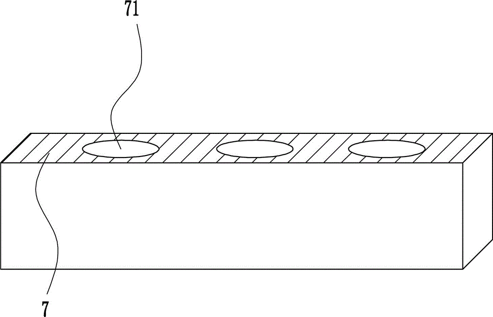
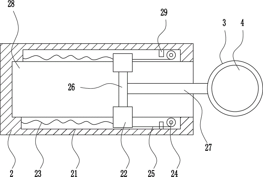
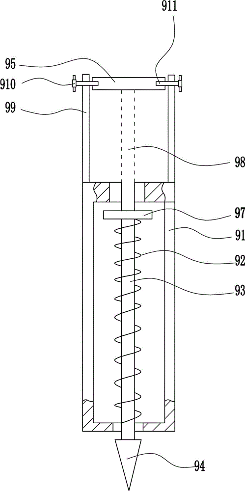
[0032] A new type of feeder, such as Figure 1-9 As shown, it includes a hopper lifting feeder 1, a mounting plate 2, a slide rail 21, a slider 22, a first spring 23, an electric wheel 24, a wire rope 25, a moving plate 26, a connecting rod 27, a travel switch 29, and a bucket 3 , working hopper 4, annular bump 41, roller 5, clamping device 6, first clamping plate 7, cone bucket 8, dredging device 9, pole 10 and discharge butterfly valve 11, the bottom of the hopper lifting feeder 1 is connected by bolts The mounting plate 2 is connected with the mounting plate 2, and a through hole 28 is opened on the mounting plate 2. Both the front and rear walls of the mounting plate 2 are connected with a slide rail 21 by means of bolt connection, and the right side of the inner wall of the slide rail 21 is connected by a screw connection. A travel switch 29 is connected, a slide block 22 is slidably connected on the slide rail 21, a first spring 23 is connected between the left wall of t...

Embodiment 2

[0034] A new type of feeder, such as Figure 1-9 As shown, it includes a hopper lifting feeder 1, a mounting plate 2, a slide rail 21, a slider 22, a first spring 23, an electric wheel 24, a wire rope 25, a moving plate 26, a connecting rod 27, a travel switch 29, and a bucket 3 , working hopper 4, annular bump 41, roller 5, clamping device 6, first clamping plate 7, cone bucket 8, dredging device 9, pole 10 and discharge butterfly valve 11, the bottom of the hopper lifting feeder 1 is connected by bolts The mounting plate 2 is connected with the mounting plate 2, and a through hole 28 is opened on the mounting plate 2. Both the front and rear walls of the mounting plate 2 are connected with a slide rail 21 by means of bolt connection, and the right side of the inner wall of the slide rail 21 is connected by a screw connection. A travel switch 29 is connected, a slide block 22 is slidably connected on the slide rail 21, a first spring 23 is connected between the left wall of t...

Embodiment 3

[0037] A new type of feeder, such as Figure 1-9 As shown, it includes a hopper lifting feeder 1, a mounting plate 2, a slide rail 21, a slider 22, a first spring 23, an electric wheel 24, a wire rope 25, a moving plate 26, a connecting rod 27, a travel switch 29, and a bucket 3 , working hopper 4, annular bump 41, roller 5, clamping device 6, first clamping plate 7, cone bucket 8, dredging device 9, pole 10 and discharge butterfly valve 11, the bottom of the hopper lifting feeder 1 is connected by bolts The mounting plate 2 is connected with the mounting plate 2, and a through hole 28 is opened on the mounting plate 2. Both the front and rear walls of the mounting plate 2 are connected with a slide rail 21 by means of bolt connection, and the right side of the inner wall of the slide rail 21 is connected by a screw connection. A travel switch 29 is connected, a slide block 22 is slidably connected on the slide rail 21, a first spring 23 is connected between the left wall of t...


PUM


Abstract

The invention relates to a feeder, particularly to a novel feeder, and provides the novel feeder which can accurately enable a working hopper to be right below a conical funnel, facilitates dredging of the conical funnel, and is aimed at solving the technical problem. The novel feeder provided to solve the technical problem comprises a hopper lifting feeding machine, a mounting plate, slide rails, sliding blocks, first springs, electric wheels, steel wire ropes, a movable plate, a connecting rod, travel switches, a placing bucket, and the like, wherein the mounting plate is in bolted connection with the bottom of the hopper lifting feeding machine; a through hole is formed in the mounting plate; the slide rails are in bolted connection with the front and back walls in the mounting plate; and the travel switches are in screw connection with the right sides of the inner walls of the slide rails. According to the novel feeder designed by the invention, the placing bucket and the hopper lifting feeding machine are combined, and the placing bucket can move left and right.

Description

technical field [0001] The invention relates to a feeder, in particular to a novel feeder. Background technique [0002] The hopper lifting feeder is mainly composed of a fixed chassis, a column, a hydraulic lifting system, a horizontal rotation and a brake mechanism. When working, start the operating lever on the control panel, lift the mixing working hopper into place, rotate the machine base horizontally, start the brake device, the working hopper of the feeder is docked with the equipment inlet of the next process and sealed, and the working hopper on the working hopper is turned on. The discharge butterfly valve can be used for feeding. [0003] The current hopper lifting feeder manually moves the loaded working hopper to the bottom of the cone, and buckles the working hopper and the cone. Due to manual operation, it is impossible to accurately position the working hopper in the cone with the naked eye. It needs to be adjusted many times, which takes a long time and r...

Claims


Application Information

Patent Timeline
Patent Type & Authority Applications(China)
IPC IPC(8): B65G47/90B65D88/68
CPCB65D88/68B65G47/902
Inventor 不公告发明人
Owner 新昌县云大农业有限公司
Why Eureka
Try Eureka