Shaft cast-plugging device and mounting method thereof

A technology of wellbore and barrel, applied in the field of wellbore plugging device and its installation, can solve the problems of safety risk and complicated operation, and achieve the effects of low operating cost, short well occupancy time and simple operation

Active Publication Date: 2017-03-22
新疆能新科油气技术有限公司 +1
View PDF11 Cites 3 Cited by
  • Summary
  • Abstract
  • Description
  • Claims
  • Application Information

AI Technical Summary

Problems solved by technology

[0004] The purpose of the present invention is to provide a wellbore plugging device and its installation method to solve the problems in the prior art that there are safety risks and complex operations when killing wells or using blowout prevention equipment before the tubing or oil well pump is lowered. technical issues

Method used


Image

  • Shaft cast-plugging device and mounting method thereof
  • Shaft cast-plugging device and mounting method thereof
  • Shaft cast-plugging device and mounting method thereof

Examples


Embodiment 1

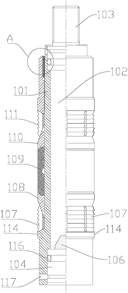
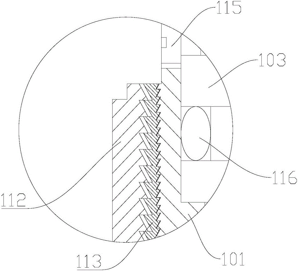
[0035] See figure 1 with figure 2 As shown, the first embodiment of the present invention provides a wellbore plugging device, including a plugging barrel 101. The plugging barrel 101 has a hollow cavity 102; the plugging barrel 101 also has corresponding head and tail ends. Specifically, the head end and the tail end of the plugging cylinder 101 are located in the axial direction of the hollow cylinder cavity 102; the head end is equipped with a drop connector 103 for connecting with the setting tool, and the tail end is equipped with a seal The plug 104, and the sealing plug 104 is located in the hollow cylinder cavity 102, the sealing plug 104 is made of degradable material; the outer surface of the plugging cylinder 101 is provided with a plugging mechanism for fixing the plugging cylinder 101 in the oil well , About to set the plugging cylinder 101 in the casing 105 of the oil well.

[0036] When in use, it is convenient to set the plugging barrel 101 in the casing 105 of t...

Embodiment 2

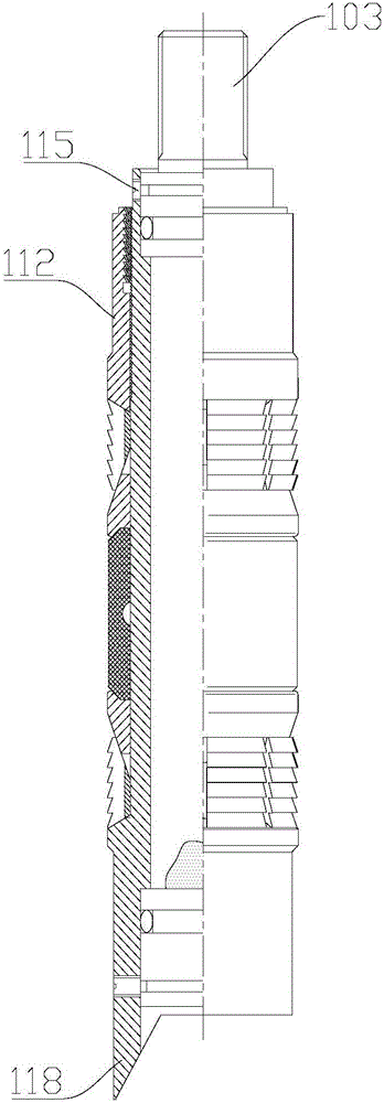
[0048] See image 3 As shown, the wellbore plugging device in the second embodiment is an improvement on the basis of the first embodiment. The technical content disclosed in the first embodiment is not described repeatedly, and the content disclosed in the first embodiment also belongs to the content disclosed in this embodiment.

[0049] The second embodiment of the present invention provides a wellbore plugging device. The end of the plugging barrel 101 has a stopper 118 for stopping the rotation of the plugging barrel 101, that is, when the wellbore plugging device After being set in the casing 105 of the oil well, the stopper 118 provided at the end of the wellbore plugging device can prevent the plugging barrel 101 from rotating; in addition, when the degradation function of the sealing plug 104 fails, the tool can be used to The second shear nail 117 is cut, so that when the sealing plug 104 is separated from the plug-in barrel 101, it can also serve to block the downward m...

Embodiment 3

[0051] See Figure 4 to Figure 7 As shown, the third embodiment of the present invention provides a method for installing the wellbore plugging device 100, where the wellbore plugging device 100 is the wellbore plugging device 100 in the first or second embodiment, and includes the following steps:

[0052] Step S100: Install the wellbore plugging device 100 on the setting tool. Specifically, the setting tool is a cable setting tool 119. The wellbore plugging device 100 and the cable setting tool 119 are connected, and the two are placed in the blowout preventer 121.

[0053] Step S200: Put the installed wellbore plugging device 100 and the setting tool into the casing 105 in the oil well, and lowering the wellbore plugging device 100 and the setting tool to a predetermined position in the oil well. Specifically, the blowout preventer 121 is lifted with a crane 124, and the blowout preventer 121 is connected to the wellhead of the oil well; the wellhead control valve is opened, an...


PUM


Abstract

The invention relates to the technical field of oil well control equipment, in particular to a shaft cast-plugging device and a mounting method thereof. The shaft cast-plugging device comprises a cast-plugging barrel which is provided with a hollow barrel cavity, a head end and a tail end corresponding to the head end. A releasing sub is mounted at the head end, and a sealing plug is mounted at the tail end, located in the hollow barrel cavity and made of degradable materials. A blocking mechanism is arranged on the outer surface of the cast-plugging barrel. A blocking part is arranged at the tail end of the shaft cast-plugging device. The mounting method of the shaft cast-plugging device includes the following steps that the shaft cast-plugging device and a setting tool mounted together with the shaft cast-plugging device are placed in a sleeve in an oil well, the shaft cast-plugging device and the setting tool are downwards placed in a predetermined position in the oil well, and the setting tool and the shaft cast-plugging device are separated. According to the shaft cast-plugging device and the mounting method thereof, operation safety and construction efficiency are improved greatly, and the shaft cast-plugging device has the characteristics that operation is easy, the operation cost is low, and the well occupying time is short.

Description

Technical field [0001] The invention relates to the technical field of oil well well control equipment, in particular to a wellbore plugging device and an installation method thereof. Background technique [0002] After the fracturing operation is completed, some existing wells need to run tubing or pumps to meet the optimal production demand. However, the formation after fracturing stores higher pressure energy, and the tubing or pumps are run The well must be killed or blowout prevention equipment must be used. [0003] However, well killing operations not only have the risk of contaminating the formations, but also often require repeated killings due to unsuccessful well killings, and the operations are complicated. When blowout prevention equipment is used, the operations are complicated, the operating costs are relatively high, and the well time is long. , There are still a lot of security risks. Summary of the invention [0004] The purpose of the present invention is to pro...

Claims


Application Information

Patent Timeline
Patent Type & Authority Applications(China)
IPC IPC(8): E21B33/12
CPCE21B33/12E21B33/1208
Inventor 章敬张亚杰李颖李见王腾飞万楷
Owner 新疆能新科油气技术有限公司
Why Eureka
Try Eureka