Antenna directional pattern-based method for correcting RCS of calculation target

An antenna pattern and correction calculation technology, applied in radio wave measurement systems, instruments, etc., can solve the problem of the influence of the antenna pattern that cannot be corrected, and achieve the effect of simplifying complexity and reducing errors

Inactive Publication Date: 2017-03-22
NORTHWESTERN POLYTECHNICAL UNIV
View PDF5 Cites 13 Cited by
  • Summary
  • Abstract
  • Description
  • Claims
  • Application Information

AI Technical Summary

Problems solved by technology

[0003] In order to overcome the problem that the existing method cannot correct the influence of the antenna pattern, the present invention provides a method for correcting and calculating the target RCS based on the antenna pattern

Method used


Image

  • Antenna directional pattern-based method for correcting RCS of calculation target
  • Antenna directional pattern-based method for correcting RCS of calculation target
  • Antenna directional pattern-based method for correcting RCS of calculation target

Examples


Embodiment Construction

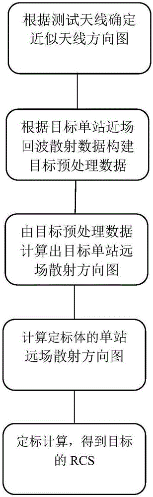
[0028] The present invention will be further described below in conjunction with the accompanying drawings and embodiments, and the present invention includes but not limited to the following embodiments.

[0029] 1. Determine the approximate antenna pattern

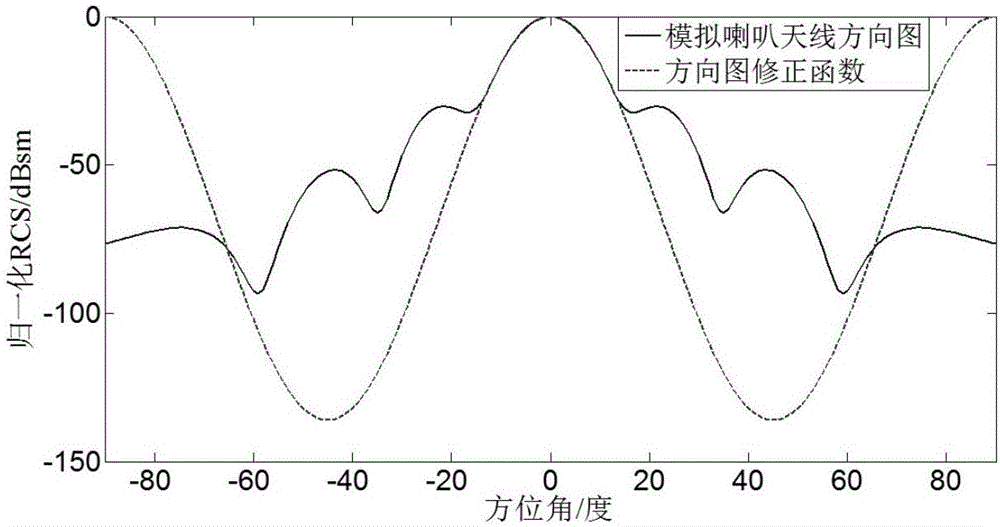
[0030] Approximate the pattern function of the known test antenna, so that the maximum error between the approximate function and the pattern function in the angular range of the antenna irradiating the target is less than 0.5dB. Generally, the trigonometric function 10 can be used A·((B*cos(Cψ)-B) / 10) Approximate the pattern function of the test antenna, and obtain the approximate antenna pattern by changing the values ​​of A, B, and C. The higher the approximation accuracy, the more accurate the correction.

[0031] In this example, the horn antenna is used as the transmitting and receiving antenna of the measurement system, and the periodic function 10 is used 4·((17*cos(4ψ)-17) / 10) As an approximate pattern function...


PUM


Abstract

The present invention provides an antenna directional pattern-based method for correcting the RCS of a calculation target. The imaging-based near-field and far-field transformation method is adopted as a basis, and the microwave imaging concept is introduced to establish the relationship among the two-dimensional image, the near-field echo and the scattering characteristics of a target. The accurate extrapolation of near-field data is realized without the need of imaging during the treatment process. Since the influence of an antenna directional pattern is considered during the echo scattering process of the near-field echo of a single station, the data representation of a target near-field is more accurate. An approximate antenna directional pattern function, instead of an actual antenna directional pattern function, is adopted. During the extrapolation process, the influence of the antenna directional pattern is corrected. Therefore, the construction complexity of the directional pattern function is simplified. Meanwhile, the calculation error of the target RCS is reduced.

Description

technical field [0001] The invention belongs to the field of microwave measurement, and in particular relates to a method for correcting the influence of an antenna pattern on near-field echo scattering data of a single station, and extrapolating to obtain a target RCS. Background technique [0002] In order to better design and evaluate the stealth performance of weapons, it is necessary to accurately measure the RCS of the target. Measuring RCS requires meeting the far-field measurement conditions over the test distance. Conventional RCS measurement methods mainly include outdoor RCS test field measurement, compact field shrinkage measurement and indoor microwave anechoic chamber measurement, all of which have developed to a fairly mature stage. Both the large outdoor field and the compact field can meet the far-field test distance required to measure the target RCS. However, the outdoor field is greatly affected by the weather and environment, and the confidentiality is...

Claims


Application Information

Patent Timeline
Patent Type & Authority Applications(China)
IPC IPC(8): G01S7/41
CPCG01S7/41
Inventor 胡楚锋徐志浩陈卫军张麟兮
Owner NORTHWESTERN POLYTECHNICAL UNIV
Why Eureka
Try Eureka