Control method for optimizing dynamic backlight of local area of liquid crystal display equipment

A technology of local area and control method, applied in static indicators, instruments, etc., can solve the problems of incomplete reproduction of image content, high output light, sudden changes in backlight, etc., to achieve optimized display uniformity, prominent leading role, and high contrast. Effect

Active Publication Date: 2017-03-22
SOUTHEAST UNIV
View PDF4 Cites 13 Cited by
  • Summary
  • Abstract
  • Description
  • Claims
  • Application Information

AI Technical Summary

Problems solved by technology

[0003] The traditional liquid crystal display cannot fully reproduce the image content in the dark field, due to the incomplete closing defect of the liquid crystal molecules, the local dynamic backlight technology is used to overcome the defects of the liquid crystal material itself
However, for existing dynamic backlight liquid crystal display devices, the traditional local dynamic backlight algorithm has the following defects: (1) For the situation of high image contrast, due to the incomplete closing of the liquid crystal, the backlight of the brighter partition causes the outgoing light to be too high, As a result, the backlight mutation of moving images is caused; (2) due to the overly conservative backlight estimation, the backlight reduction for most images is insufficient, and the energy saving is limited
For the liquid crystal display of mobile devices, due to the limitation of cost, driving circuit area and other conditions, only dynamic backlight with fewer partitions can be used, which will lead to more serious backlight mutation and seriously affect the display effect

Method used


Image

  • Control method for optimizing dynamic backlight of local area of liquid crystal display equipment
  • Control method for optimizing dynamic backlight of local area of liquid crystal display equipment
  • Control method for optimizing dynamic backlight of local area of liquid crystal display equipment

Examples


Embodiment Construction

[0024] The present invention will be further described below in conjunction with the accompanying drawings.

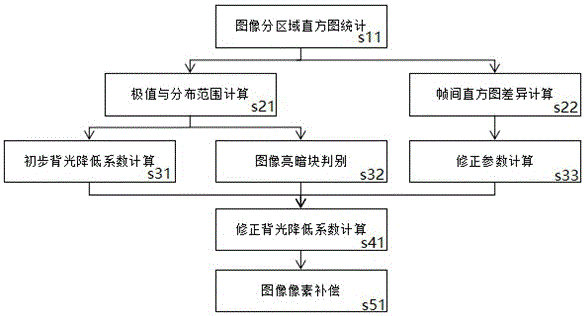
[0025] Such as figure 1 As shown, the specific implementation flow chart of the present invention is as follows, wherein the method for dynamic backlight control is specifically shown:

[0026] S11. Obtain the gray value of all pixels under each block through statistics, and then perform histogram statistics by region. In the method of the present invention, RGB is used as an example for image grayscale, and the display image system is 8bit system, that is, the grayscale range is 0-255. Take the maximum value of the three RGB channels of each pixel as the final gray value of the point. Then perform histogram statistics on the interior of each partition, and obtain a list of the number of pixels at different gray levels.

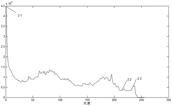
[0027] Such as figure 2 As shown, there is a histogram distribution example, the abscissa is grayscale, the distribution range is 0-255, and the...


PUM


Abstract

The invention discloses a control method for optimizing dynamic backlight of a local area of liquid crystal display equipment. The liquid crystal display effect is optimized by means of dynamic backlight modulation and image content correction. The control method comprises the steps that 1, the image gray level distribution under each subarea is detected under a fixed sub block, and brightness estimations of all subareas are obtained according to detection results; 2, an interframe histogram difference is detected, and weighted summation is performed to obtain image change estimations, and backlight correction parameters are obtained according to estimation results; 3, initial backlight is dynamically corrected through the backlight correction parameters, and backlight is controlled to be changed; and 4, image content is dynamically corrected according to the obtained backlight. By means of dynamically correcting backlight, the image signal to noise ratio can be ensured, meanwhile, energy consumption of the display equipment is lowered, the image dynamic contrast is increased, and dynamic backlight uniformity optimization is achieved, so that the purpose of optimizing the subjective display effect is achieved.

Description

technical field [0001] The invention relates to a control method for optimizing the dynamic backlight of a local area of ​​a liquid crystal display device based on probability statistics, and belongs to the field of display device algorithms. Background technique [0002] With the rapid development of display technology, people's requirements for display devices are also constantly increasing. Display devices with high color gamut, high contrast, low power consumption, and large size are gradually favored by more and more people. In addition, the development of mobile devices also puts forward more new requirements for display functions. [0003] The traditional liquid crystal display cannot fully reproduce the image content in the dark field, due to the incomplete closing defect of the liquid crystal molecules, the local dynamic backlight technology is used to overcome the defects of the liquid crystal material itself. However, for the existing dynamic backlight liquid cr...

Claims


Application Information

Patent Timeline
Patent Type & Authority Applications(China)
IPC IPC(8): G09G3/34G09G3/36
CPCG09G3/3406G09G3/3607G09G2320/0233
Inventor 冯鲲鹏王坚李晓华
Owner SOUTHEAST UNIV
Why Eureka
Try Eureka