Switch cabinet box body

A switchgear and box technology, applied in substation/switch layout details, substation/switchgear cooling/ventilation, electrical components, etc., to ensure the effect of sealing stability

Inactive Publication Date: 2017-03-22
ANHUI ROBUTEC
View PDF7 Cites 0 Cited by
  • Summary
  • Abstract
  • Description
  • Claims
  • Application Information

AI Technical Summary

Problems solved by technology

[0005] The purpose of the present invention is to provide a switchgear box, which overcomes the problem that the switchgear box in the prior art cannot ensure its sealing under the condition of satisfying its good heat dissipation

Method used


Image

  • Switch cabinet box body

Examples


Embodiment Construction

[0022] Specific embodiments of the present invention will be described in detail below in conjunction with the accompanying drawings. It should be understood that the specific embodiments described here are only used to illustrate and explain the present invention, and are not intended to limit the present invention.

[0023] In the present invention, unless stated otherwise, the used orientation words such as "up, down, left, right" usually refer to figure 1 Up and down and left and right are shown. "Inner and outer" refer to the inner and outer on the specific outline. "Far and near" refer to far and near relative to a certain component.

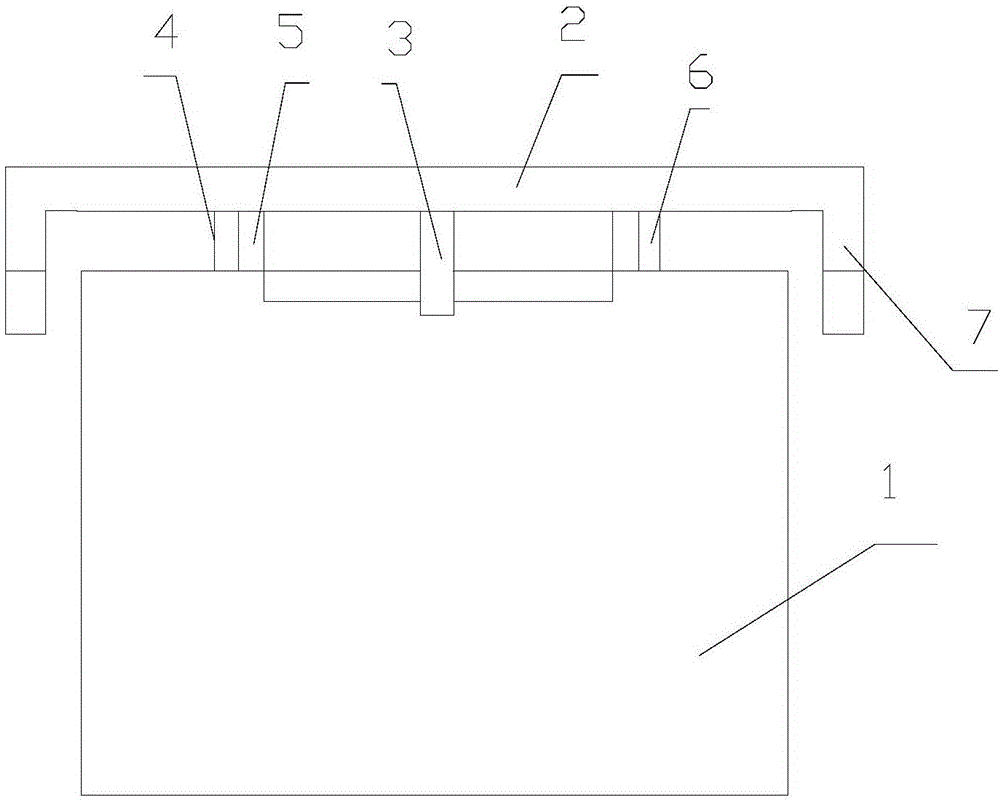
[0024] The present invention provides a switchgear box, the switchgear box includes: a shell 1, a top plate 2 and a first ventilation fan 3, the top of the shell 1 is provided with an opening, and the top plate 2 is arranged on the shell along the horizontal direction 1, and the periphery of the top plate 2 protrudes from the shell 1, a...


PUM


Abstract

The invention discloses a switch cabinet box body, which comprises a housing (1), a top plate (2) and a first ventilation fan (3), wherein an opening is formed in the top of the housing (1); the top plate (2) is arranged at the vertical upper part of the housing (1) along a horizontal direction and the periphery of the top plate (2) protrudes out of the housing (1); a flange (7) is arranged on the periphery of the top plate (2) along a vertical downward direction; a support part (4) is arranged between the housing (1) and the top plate (2); the first ventilation fan (3) is fixedly connected to the top plate (2) and arranged in the opening; and an air outlet end of the first ventilation fan (3) faces toward the outside of the housing (1). According to the switch cabinet box body, the problem that the switch cabinet box body cannot ensure the air-tightness under the condition of meeting good heat dissipation in the prior art is solved.

Description

technical field [0001] The invention relates to the field of electrical switch cabinets, in particular to a switch cabinet box body. Background technique [0002] The switch cabinet is a kind of electrical equipment. The outside line of the switch cabinet first enters the main control switch in the cabinet, and then enters the sub-control switch. Each branch is set according to its needs. Such as instruments, automatic controls, motor magnetic switches, various AC contactors, etc., some also have high-voltage room and low-voltage room switch cabinets, high-voltage busbars, such as power plants, etc. load shedding. [0003] The main function of the switchgear is to open and close, control and protect electrical equipment during the process of power generation, transmission, distribution and power conversion in the power system. The components in the switch cabinet are mainly composed of circuit breakers, disconnectors, load switches, operating mechanisms, transformers and v...

Claims


Application Information

Patent Timeline
IPC IPC(8): H02B1/28H02B1/56
CPCH02B1/28H02B1/565
Inventor 蔡旭张长君郭家虎黄云闻易咏波魏振超
Owner ANHUI ROBUTEC
Why Eureka
Try Eureka