Power distribution cabinet for workshop

A power distribution cabinet and power technology, which is applied in electrical components, circuit devices, emergency power supply arrangements, etc., can solve the problems of inconvenient operation and maintenance, lack of management, and difficulty in placing wire troughs, so as to facilitate timely observation and improve safety performance. , the effect of improving stability

Inactive Publication Date: 2017-03-22
安徽永川电气设备有限公司
View PDF4 Cites 2 Cited by
  • Summary
  • Abstract
  • Description
  • Claims
  • Application Information

AI Technical Summary

Problems solved by technology

[0002] As an indispensable power distribution auxiliary equipment for automatic production, the power distribution cabinet is self-evident. Because there are many cables entering and leaving the power distribution cabinet, the existing power distribution cabinet looks very messy and it is difficult to find it quickly. Corresponding to the location of the cables; especially for cables with large current loads, because the cables are relatively thick, it is difficult to put them in the wire slots of the existing power distribution cabinets
Most of the power distribution cabinets in the prior art use uninterruptible power distribution cabinets with their own batteries. Therefore, multiple battery packs are installed in the power distribution cabinet. It is well known that each storage battery has internal resistance, and the internal resistance of the battery Resistance is an important performance indicator of the battery, and the existing power distribution cabinets have low degree of automation, lack of management, and poor economy, resources cannot be comprehensively utilized, installation service coordination is difficult, operation and maintenance are inconvenient, and information is difficult to share and operate , the system lacks scalability, and there is not enough design space for the space environment of the power distribution cabinet, such as access control, temperature and humidity, smoke, etc.

Method used


Image

  • Power distribution cabinet for workshop

Examples


Embodiment Construction

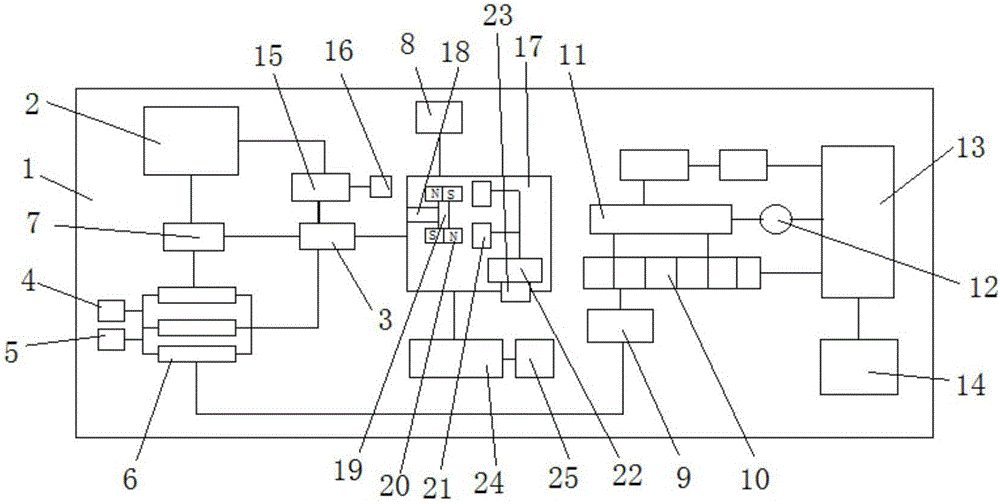
[0009] Referring to the accompanying drawings, a power distribution cabinet for a workshop includes a cabinet body 1, a mains power input terminal 2, the mains power input terminal 2 is connected to the mains, and an inverter switching module 3, and the mains power input module 2 is provided with a DC power input module 4, the DC power input module 4 and the AC power input module 5, the DC power input module 4 and the AC power input module 5 are respectively connected to a plurality of power UPS modules 6, the city Between the electric power source 2 and the power UPS module 6 are connected monitors 7 that can detect their respective performances. The monitors 7 are connected to the mains and inverter switching modules 3, and the three mains and inverter switching modules are connected to external The load 8, the power UPS module 6 and the mains power supply input terminal 2 are respectively connected to the charging module 9, and the charging module 9 is connected to the batte...


PUM


Abstract

The invention discloses a power distribution cabinet for a workshop. The power distribution cabinet comprises a cabinet body and a commercial power source input module; the power distribution cabinet is characterized in that the commercial power source input module is connected with a commercial power inverter switching module; a DC power supply input module is arranged below the commercial power source input module; the DC power supply input module and an AC power supply input module are connected with a plurality of power UPS modules respectively; and a monitor capable of detecting respective performance separately is connected between the commercial power source input module and the power UPS modules. An electric switch is arranged on an output circuit of the monitor and is in control connection through an infrared module, so that remote control is achieved and the security performance is improved; and a multi-path switching circuit module is arranged on a storage battery pack and is connected with a current collection module, and the current collection module is connected to an MCU master controller, so that the performance condition of the storage battery pack is convenient to timely monitor.

Description

technical field [0001] The invention relates to the technical field of power distribution cabinets, in particular to a power distribution cabinet for workshops. Background technique [0002] As an indispensable power distribution auxiliary equipment for automatic production, the power distribution cabinet is self-evident. Because there are many cables entering and leaving the power distribution cabinet, the existing power distribution cabinet looks very messy and it is difficult to find it quickly. Corresponding to the location of the cables; especially for cables with large current loads, because the cables are relatively thick, it is difficult to put them in the wire slots of the existing power distribution cabinets. Most of the power distribution cabinets in the prior art use uninterruptible power distribution cabinets with their own batteries. Therefore, multiple battery packs are installed in the power distribution cabinet. It is well known that each storage battery has...

Claims


Application Information

Patent Timeline
Patent Type & Authority Applications(China)
IPC IPC(8): H02J13/00H02J9/06
CPCH02J9/061H02J13/0006Y02B70/30Y02B90/20Y04S20/12Y04S20/248
Inventor 孙永霞
Owner 安徽永川电气设备有限公司
Why Eureka
Try Eureka