Supercharge Your Innovation With Domain-Expert AI Agents!

Power conversion method and system

A power conversion and slew rate technology, applied in the system field, can solve problems such as low impedance

Active Publication Date: 2017-03-22
凯文·史蒂芬·戴维斯 +1
View PDF4 Cites 3 Cited by
  • Summary
  • Abstract
  • Description
  • Claims
  • Application Information

AI Technical Summary

Problems solved by technology

However, due to the low impedance of the power supply and the very low impedance of the switching memory device in series, higher voltage surges can generate damaging high currents into the memory device

Method used


Image

  • Power conversion method and system
  • Power conversion method and system
  • Power conversion method and system

Examples


Embodiment Construction

[0074] DETAILED DESCRIPTION OF THE PREFERRED EMBODIMENT

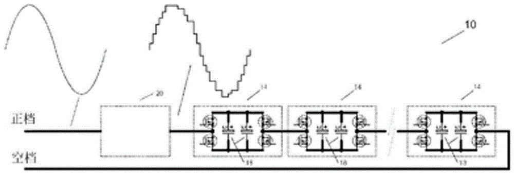
[0075] The power conversion system 10 is generally of the type described by the applicant in earlier international patent applications WO2012 / 016285 and WO2013 / 023248. figure 1 The overall elements of system 10 are represented as shown.

[0076] The power conversion system 10 includes a plurality of modules 14, each module 14 being associated with at least one power source. The power source can be, for example, a solar panel or a battery.

[0077] Each module 14 is also provided with a storage device 18 and is connected to terminals of a power supply. Storage device 18 may include an electrolytic capacitor or such a battery that can efficiently and reliably supply pulsed current. The storage device 18 is charged by the power source so that when the module 14 is bypassed, the power generated by the power source continues to be stored in the storage device 18 for future use. The storage device 18 may be independent of...


PUM


Abstract

A system for converting power comprising a plurality of modules comprising a storage device, connected in series and having each at least one DC power source. A voltage control circuitry in each module connects the storage device between a maximum and minimum module voltage to create a stepwise approximation of a mains signal. A compensator unit is provided in series with the modules including a storage device charged by the power sources. A control unit is used to ramp up or down the voltage between the input and output of the compensator unit to follow the desired AC signal. When the control unit operates a module to vary the supplied voltage from either zero to the maximum or minimum values, or vice versa, the control unit applies via compensator voltage control circuitry a corresponding but opposed change in the voltage supplied by the compensator unit.

Description

technical field [0001] The present invention relates to a system and method for power conversion between DC power and AC power. Background technique [0002] There are currently many applications for conversion between DC power and AC power. Earlier international patent applications, application numbers WO2012 / 016285 and WO2013 / 023248, disclose systems with methods to facilitate this conversion. [0003] The system is used to generate an AC signal suitable for power supply or injection into a mains power supply from a DC power supply comprising a set of modules connected in series, each module being connected to a DC power supply. The modules are switched out of series to form a gradual approximation of an AC signal, while further ramp changes bring the signal closer to a smooth AC signal. [0004] The systems described in WO2012 / 016285 and WO2013 / 023248 use switching regulators in each module. Using a pulse width modulated signal, the switching regulator regulates the vo...

Claims


Application Information

Patent Timeline
Patent Type & Authority Applications(China)
IPC IPC(8): G01F1/10H02M7/02
CPCH02M1/12H02M7/49Y02E10/50Y02B70/10H02M1/0054H02H9/026H02M7/483H02M7/4835Y02E60/10H02M3/135H02M7/48H02S10/00H01M10/441H02J7/0013H02J7/007
Inventor 凯文·史蒂芬·戴维斯亚力山大·菲利普·戴维斯
Owner 凯文·史蒂芬·戴维斯
Features
  • R&D
  • Intellectual Property
  • Life Sciences
  • Materials
  • Tech Scout
  • Unparalleled Data Quality
  • Higher Quality Content
  • 60% Fewer Hallucinations
Learn More