Ultrasonic breast inspection instrument

An ultrasonography instrument and examination instrument technology, applied in mammography, ultrasound/sonic wave/infrasonic wave diagnosis, ultrasound/sonic wave/infrasonic wave Permian technology, etc., can solve human discomfort, easy movement and deformation of the target body, and ultrasonic scanning The result does not add accuracy and other problems, to achieve the effect of improving accuracy

Inactive Publication Date: 2017-03-29
SHANTOU INST OF UITRASONIC INSTR CO LTD
View PDF8 Cites 15 Cited by
  • Summary
  • Abstract
  • Description
  • Claims
  • Application Information

AI Technical Summary

Problems solved by technology

[0002] In the current ultrasonic scanning device, the ultrasonic probe is generally in direct contact with the human body. During the scanning process of the ultrasonic probe, the target body is easy to move and deform, resulting in inaccurate ultrasonic scanning results. In addition, the ultrasonic probe is in direct contact with the human body. The process causes discomfort to the human body
[0003] Another ultrasonic scanning device, in order to solve the problem of scanning the concave and convex parts of the human body, for example, a breast ultrasound examination instrument for breast scannin

Method used


Image

  • Ultrasonic breast inspection instrument
  • Ultrasonic breast inspection instrument
  • Ultrasonic breast inspection instrument

Examples


Embodiment 1

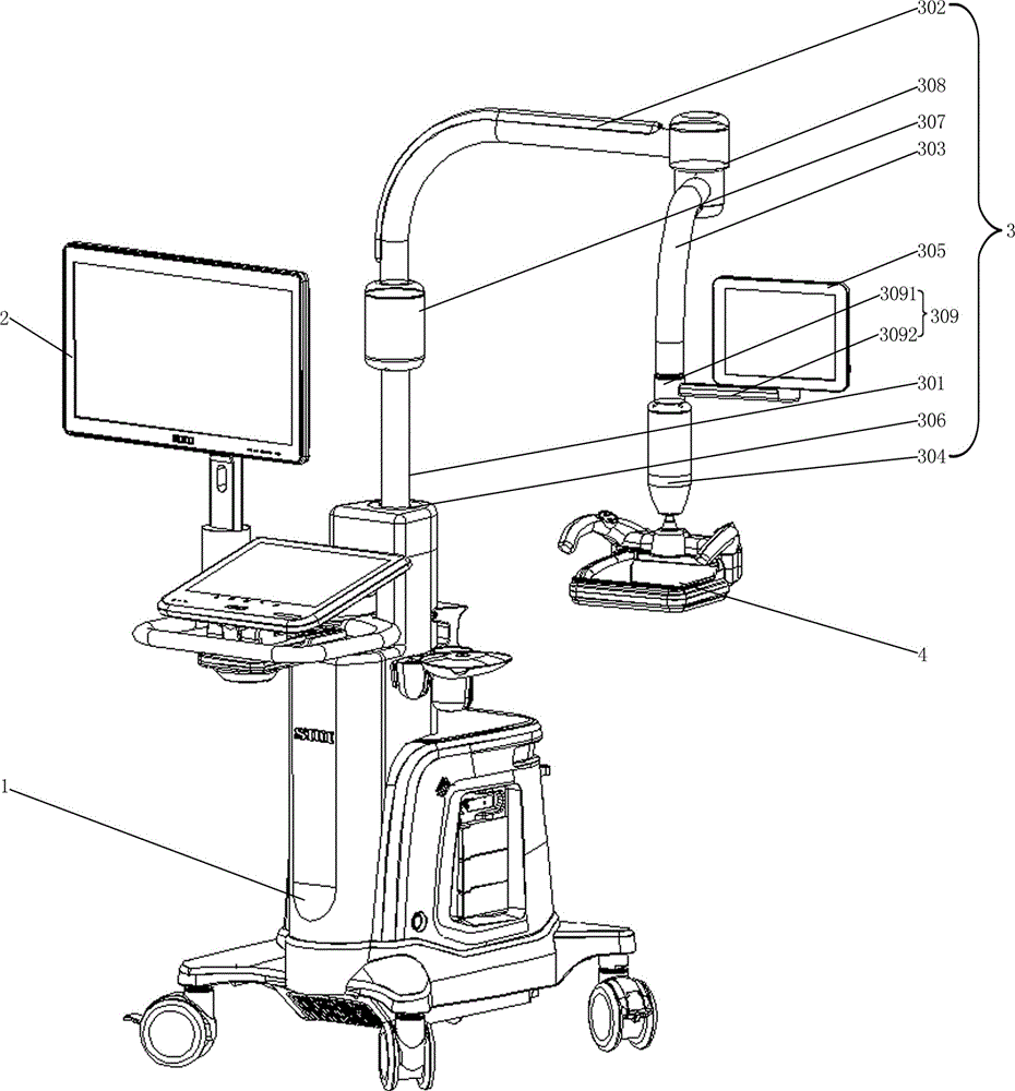
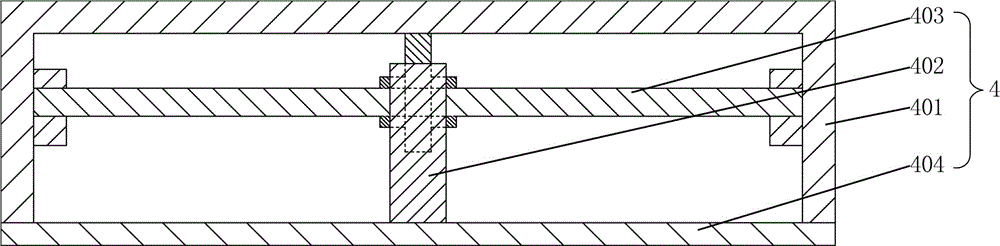
[0033] Such as figure 1 As shown, this mammary gland ultrasonography instrument includes an examination instrument main body 1, a first display 2, a support arm 3 and an ultrasonic scanning device 4, the first display 2 is installed on the examination instrument main body 1, and one end of the support arm 3 is installed on the On the inspection instrument main body 1, the ultrasonic scanning device 4 is installed on the other end of the support arm 3; as figure 2 As shown, the ultrasonic scanning device 4 includes a housing 401, an ultrasonic probe 402, and a probe moving device 403 capable of moving the ultrasonic probe 402. The bottom of the housing 401 is provided with a hard base plate 404; the ultrasonic probe 402 and the probe moving device 403 are all installed in the housing. In 401 , the lower end surface of the ultrasonic probe 402 is in contact with the upper surface of the hard base plate 404 and coupled through a coupling agent.

[0034] The above-mentioned prob...

Embodiment 2

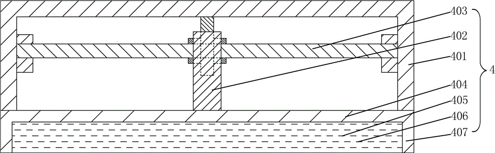
[0040] Such as image 3 As shown, on the basis of Embodiment 1, the ultrasonic scanning device 4 adds a coupling capsule 405, and the coupling capsule 405 is filled with a coupling agent 406; wherein, the edge of the hard base plate 404 extends downward to form a coupling cavity 407, and the coupling capsule 405 is installed in the coupling cavity 407 , and the upper side of the coupling bag 405 is in close contact with the lower surface of the hard bottom plate 404 .

Embodiment 3

[0042] Such as Figure 4 , Figure 5 As shown, in the case that other parts are the same as in Embodiment 1, the only difference is that: the cross section of the hard base plate 404 of the ultrasonic scanning device 4 is set to be arc-shaped; the probe moving device 403 includes a driving device ( Figure 5 not shown in), transverse guide rail 4031, transverse slider 4032, transverse encoder 4033, longitudinal guide rail 4034, longitudinal slider 4035, longitudinal encoder 4036, pressure sensor 4037 and spring 4038; the driving device and transverse guide rail 4031 are installed on In the inner cavity of the housing 401, the transverse slider 4032 is installed on the transverse guide rail 4031 and can move along the transverse guide rail 4031, the transverse encoder 4033 is arranged on the transverse slider 4032, and the power output end of the driving device is connected to the transverse slider 4032; The longitudinal guide rail 4034 is installed on the horizontal slider 40...


PUM


Abstract

An ultrasonic breast inspection instrument comprises an inspection instrument main body, a first display, a supporting arm and an ultrasonic scanning device. The first display is mounted on the inspection instrument main body. One end of the supporting arm is mounted on the inspection instrument main body, and the ultrasonic scanning device is mounted at the other end of the supporting arm and comprises a shell, an ultrasonic probe and a probe moving device capable of moving the ultrasonic probe. The bottom of the shell is provided with a hard base plate. The ultrasonic probe and the probe moving device are both mounted in the shell. The lower end face of the ultrasonic probe makes contact with and is coupled with the upper surface of the hard bottom plate. Since the ultrasonic scanning device adopts the hard bottom plate, when the ultrasonic scanning device is pressed to the human body to-be-scanned portion, the hard bottom plate can fix a target body so that the target body cannot move and deform in the scanning process of the ultrasonic probe, and an ultrasonic scanning result is more accurate accordingly; and in addition, the ultrasonic probe does not make direct contact with the human body, and discomfort caused to the human body in the scanning process is avoided.

Description

technical field [0001] The invention relates to an ultrasonic scanning device, in particular to a mammary gland ultrasonic examination instrument. Background technique [0002] In the current ultrasonic scanning device, the ultrasonic probe is generally in direct contact with the human body. During the scanning process of the ultrasonic probe, the target body is easy to move and deform, resulting in inaccurate ultrasonic scanning results. In addition, the ultrasonic probe is in direct contact with the human body. The process causes discomfort to the human body. [0003] Another ultrasonic scanning device, in order to solve the problem of scanning the concave and convex parts of the human body, for example, a breast ultrasound examination instrument for breast scanning, an elastic film is set under the ultrasonic probe, and the elastic film is used to scan the convex and convex parts of the human body. The protruding part (such as the breast) is shaped to reduce the movement...

Claims


Application Information

Patent Timeline
IPC IPC(8): A61B8/08
CPCA61B8/0825A61B8/42A61B8/4444
Inventor 李德来廖晓燕苏树钿吴晞蔡泽杭
Owner SHANTOU INST OF UITRASONIC INSTR CO LTD
Why Eureka
Try Eureka