Electronic device having liquid crystal display device

a liquid crystal display and electronic device technology, applied in static indicating devices, instruments, non-linear optics, etc., can solve problems such as poor contact, significant susceptible to characteristics variation, and faults that occur in peripheral driving circuits

Inactive Publication Date: 2002-09-12
SEMICON ENERGY LAB CO LTD
View PDF0 Cites 7 Cited by
  • Summary
  • Abstract
  • Description
  • Claims
  • Application Information

AI Technical Summary

Benefits of technology

0018] On the basis of the above-described configuration, it is another object of the invention to provide a configuration that prevents breakage of thin film transistors provided on a peripheral driving circuit due to a pressure exerted by a sealing material.

Problems solved by technology

Especially, a crystalline silicon film has a problem in that it is significantly susceptible to the variation of characteristics with time and the influence of the environment where it is used because of the high level of characteristics of itself.
Specifically, a problem arises in that it is affected by stresses exerted thereon during the fabrication and handling of a liquid crystal panel and by moisture that permeates into the liquid crystal panel.
In the case of an active matrix type liquid crystal display integrated with a peripheral driving circuit, faults that occur in the peripheral driving circuit can be a problem.
As a result, thin film transistors and wiring lines located directly under such fillers are subjected to a pressure from the fillers (it is assumed that this pressure can be locally quite high) and are hence vulnerable to line breakage and poor contact.
However, since an active matrix region is at a lower level of integration, faults attributable to the presence of a spacer are not as problematic as in a peripheral driving circuit.

Method used


Image

  • Electronic device having liquid crystal display device
  • Electronic device having liquid crystal display device
  • Electronic device having liquid crystal display device

Examples


first embodiment

[0051] the present invention will now be described.

[0052] The present embodiment employs a configuration in which a sealing material is provided on a region where a peripheral driving circuit is located. Further, in order to prevent damage to the peripheral driving circuit caused by a stress exerted by a filler included in the sealing material, a configuration is employed in which a buffer layer made of polyimide is provided on the peripheral driving circuit.

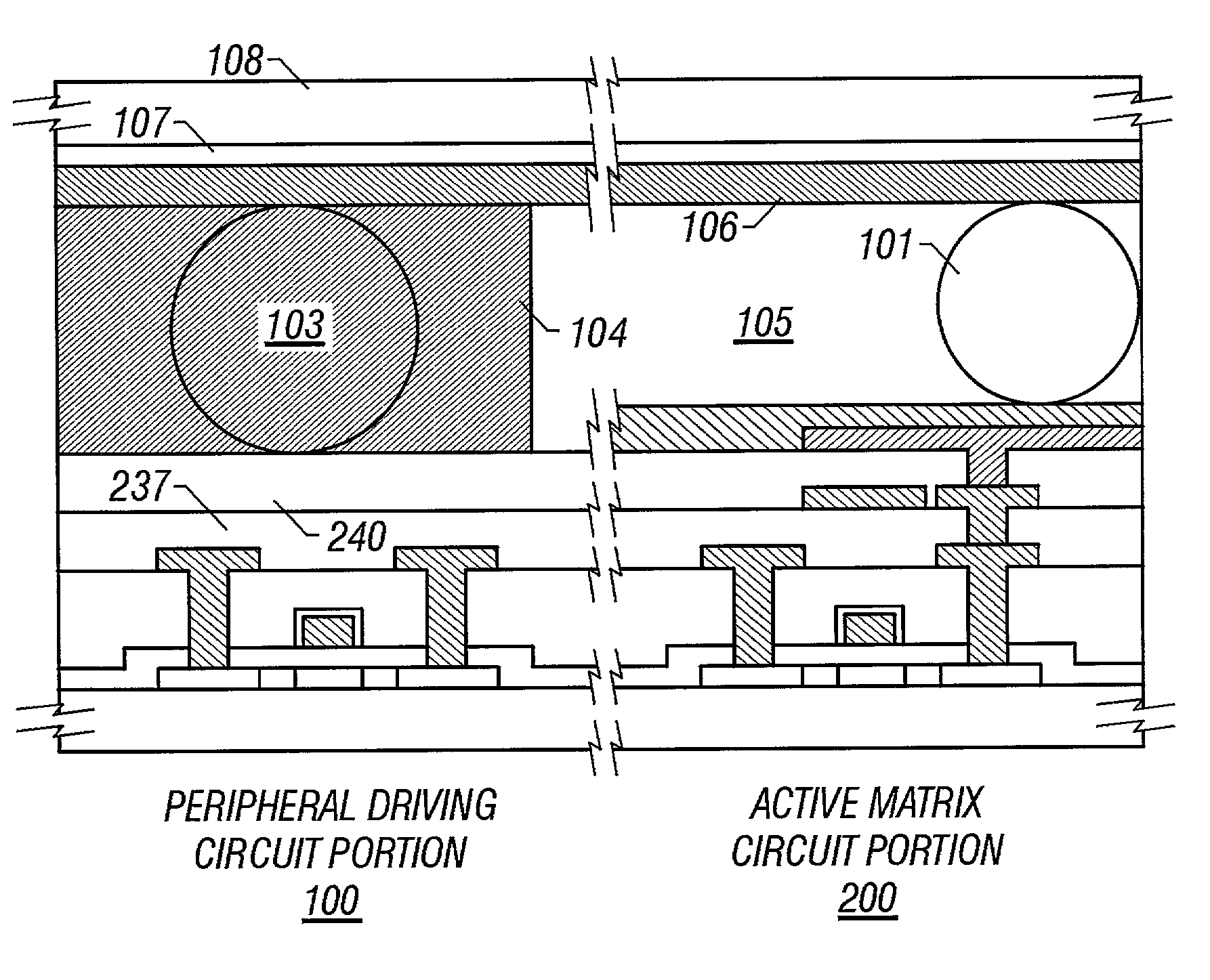
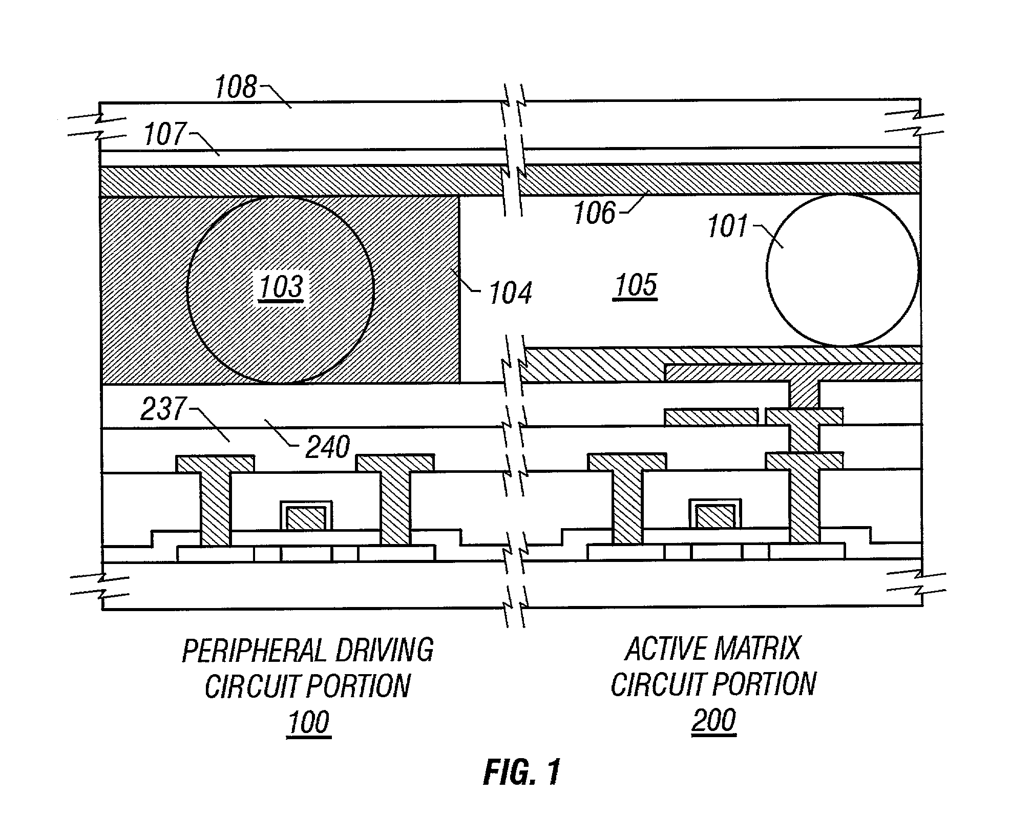
[0053] FIG. 1 is a partial sectional view of an active matrix type liquid crystal display according to the present embodiment. FIG. 1 shows a configuration referred to as "peripheral driving circuit integrated type" having a structure in which a peripheral driving circuit 100 and an active matrix circuit 200 are integrated on the same substrate.

[0054] In the configuration shown in FIG. 1, a sealing portion indicated by 104 is provided over the peripheral driving circuit 100. This sealing portion has a sealing function to prevent...

second embodiment

[0094] the present invention will now be described.

[0095] The present embodiment is an example in which bottom-gate type thin film transistors are used in a liquid crystal display integrated with a peripheral driving circuit.

[0096] FIG. 5 is a sectional view corresponding to FIG. 1. The present embodiment is different from the configuration shown in FIG. 1 in the structure of the thin film transistors. The configuration is otherwise similar to that shown in FIG. 1.

third embodiment

[0097] the present invention will now be described.

[0098] FIG. 6 schematically shows the configuration of the present embodiment. FIG. 6 is a schematic sectional view of an active matrix type liquid crystal display integrated with a peripheral driving circuit.

[0099] In FIG. 6, 301 and 318 designate a pair of glass substrates that constitute a liquid crystal panel. A liquid crystal material, an active matrix circuit, and a peripheral driving circuit for driving the active matrix circuit are provided in a gap between the pair of glass substrates.

[0100] 302 designates a thin film transistor provided in the active matrix circuit portion. Although only one thin film transistor is provided in FIG. 6, in practice, thin film transistors are provided in a quantity at least equal to the number of pixels.

[0101] 303 designates a thin film transistor provided in the peripheral driving circuit. Although only one thin film transistor 303 is provided in FIG. 6, in practice, a combination of p-chann...


PUM

PropertyMeasurementUnit
thicknessaaaaaaaaaa
thicknessaaaaaaaaaa
thicknessaaaaaaaaaa

Abstract

An electronic device having an active matrix liquid crystal device comprising a sealing layer with a region overlapping an insulating film formed over another insulating film, which extends beyond said insulating film and forms on a peripheral switching device, a region in contact with said another insulating film, and a region where said second insulating film is not formed over said another insulating film.

Description

BACKGROUND OF THE INVENTION[0001] 1. Field of the Invention[0002] The present invention relates to a configuration of an active matrix type liquid crystal display integrated with a peripheral driving circuit.[0003] 2. Description of Related Art[0004] Active matrix type liquid crystal displays have been known. They have a configuration in which an active matrix circuit and a peripheral driving circuit for driving the same circuit are integrated on a glass substrate or quartz substrate.[0005] In such a liquid crystal panel integrated with a peripheral driving circuit, a thin film semiconductor that forms thin film transistors provided in the peripheral driving circuit must be a crystalline silicon thin film. The reason for this is that the peripheral driving circuit must operate at a high speed.[0006] Reliability is an important consideration for a liquid crystal panel integrated with a peripheral driving circuit as described above. Specifically, what is important for such a device is...

Claims


Application Information

Patent Timeline
Patent Type & Authority Applications(United States)
IPC IPC(8): G02F1/1339G02F1/1362
CPCG02F1/1339G02F1/1345G02F1/13454G02F1/136277G09G3/3648G09G2320/0252G02F1/136
Inventor ZHANG, HONGYONGYAMAZAKI, SHUNPEITERAMOTO, SATOSHIHIRAKATA, YOSHIHARU
Owner SEMICON ENERGY LAB CO LTD
Why Eureka
Try Eureka