Self-cleaning type agitating vessel

A mixing tank and self-cleaning technology, which is applied to mixer accessories, mixers with rotating stirring devices, dissolution, etc., can solve problems such as large centrifugal force at the end, affecting the mixing effect, and deposition on the inner wall of the bucket, so as to achieve enhanced stability, Prevent the barrel wall deposition, the effect is good

Inactive Publication Date: 2017-03-29
苏州柯米智能科技有限公司
View PDF0 Cites 6 Cited by
  • Summary
  • Abstract
  • Description
  • Claims
  • Application Information

AI Technical Summary

Problems solved by technology

[0002] The existing stirring paddles are all fixed shapes. When stirring, the stirring effect produced is fixed. If you want to change the stirring effect, you can only achieve it by changing the stirring speed. If there are strict requirements on the stirring effect, this The stirring paddle just can't meet the demand, and the existing stirring paddle itself is all integrated, if the paddle has a certain damage, it needs to be replaced as a whole, which causes waste, because the stirring blade end of the stirring paddle used is centrifugal The effect is large, causing the end to be unstable; due to the long-time stirring in the mixing tank, it is easy to cause some deposits on the inner wall of the tank, which affects the mixing effect

Method used


Image

  • Self-cleaning type agitating vessel
  • Self-cleaning type agitating vessel
  • Self-cleaning type agitating vessel

Examples


Embodiment

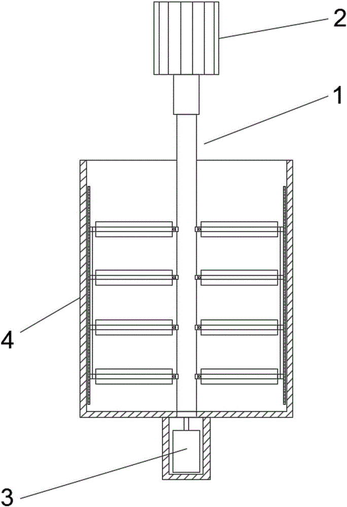
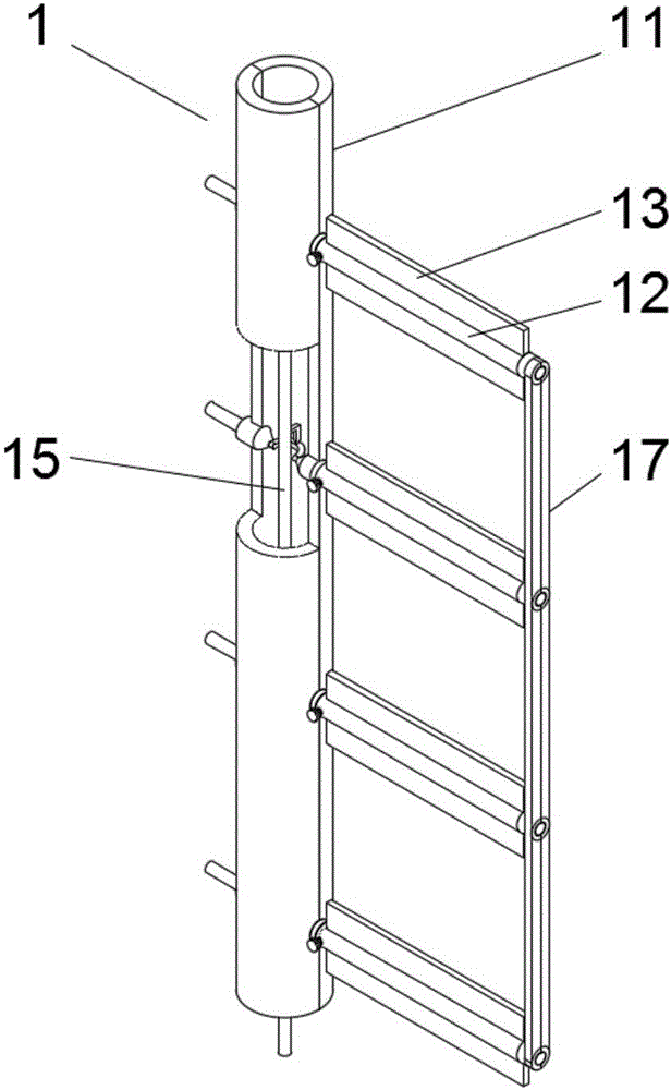
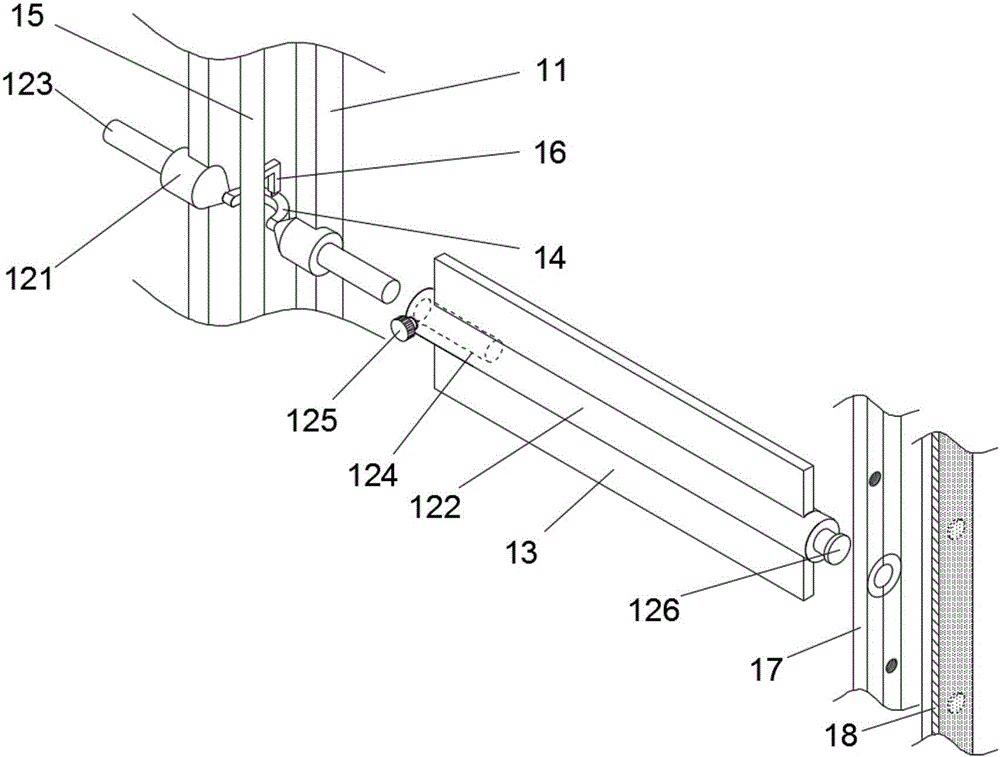
[0015] Such as Figure 1 to Figure 3 As shown, this embodiment provides a self-cleaning mixing tank, which includes a tank body 4; a stirring paddle 1 is arranged inside the tank body 4; a stirring motor 2 is connected to the top of the stirring paddle 1, and a cylinder 3 is connected to the bottom ; The stirring paddle 1 includes a hollow stirring shaft 11 composed of two semicircles; a plurality of stirring rods 12 are evenly distributed in symmetrical pairs on the stirring shaft 11; the stirring rod 12 includes a fixed part 121 and an insertion part 122; the fixed part 121 is provided with a boss 123; the insertion part 122 is provided with a hollow groove 124 used in conjunction with the boss 123; the upper and lower sides of the insertion part 122 of the stirring rod 12 are respectively provided with Stirring blades 13; the inner axis position of the stirring shaft 11 is also provided with an adjustment connecting rod 15; the inside of the stirring shaft 11 is also provid...


PUM


Abstract

The invention relates to a self-cleaning type agitating vessel. The self-cleaning type agitating vessel comprises a cylinder body; wherein a stirring paddle is arranged in the cylinder body, the stirring paddle comprises a hollow stirring shaft; stirring rods are distributed on the stirring shaft in pairs; each stirring rod comprises a fixing part and an inserting connection part; a convex column is arranged on each fixing part; a hollow slot is arranged in each inserting connection part; stirring blades are arranged on the inserting connection parts respectively; an axis location of the interior of the stirring shaft is also provided with an adjusting connecting rod; the interior of the stirring shaft is also provided with a semicircle adjusting handle; the fixing parts are connected with two ends of the adjusting handle; the adjusting connecting rod is hinged to the middle part of the adjusting handle; fixing clamp pairs of the inserting connection parts of the stirring rods arranged on the same side are provided with fixed splints in a clamping way, the outer side surface of the fixing splints are fixed with scrubbing brushes. The angle of the stirring blades in the invention can be changed in real time to change the stressing flow direction in the cylinder body, so that the stirring effect is better; when the stirring rods are damaged, the stirring rods can be replaced in time by adopting an inserting connection manner; the end part of the stirring rod is fixed through the fixing splints, so that the stability is enhanced and the stirring effect is ensured.

Description

technical field [0001] The invention relates to the field of mixing, in particular to a self-cleaning mixing tank. Background technique [0002] The existing stirring paddles are all fixed shapes. When stirring, the stirring effect produced is fixed. If you want to change the stirring effect, you can only achieve it by changing the stirring speed. If there are strict requirements on the stirring effect, this The stirring paddle just can't meet the demand, and the existing stirring paddle itself is all integrated, if the paddle has a certain damage, it needs to be replaced as a whole, which causes waste, because the stirring blade end of the stirring paddle used is centrifugal The effect is large, causing the end to be unstable; due to the long-term stirring in the mixing tank, it is easy to cause some deposits on the inner wall of the tank, which affects the mixing effect. Contents of the invention [0003] In order to solve the above technical problems, the present inven...

Claims


Application Information

Patent Timeline
Patent Type & Authority Applications(China)
IPC IPC(8): B01F7/18B01F15/00
CPCB01F27/0541B01F27/90B01F35/121B01F35/123
Inventor 周秋东
Owner 苏州柯米智能科技有限公司
Why Eureka
Try Eureka