Full-automatic seal stamping machine

A stamping machine, fully automatic technology, applied in printing, stamping and other directions, can solve the problems of inconvenient use, complex structure, manual picking and finishing, etc., saving time, high degree of automation, and enhancing functionality and practicability Effect

Active Publication Date: 2017-03-29
JINAN CITY CHANGQING DISTRICT POWER SUPPLY CO OF STATE GRID SHANDONG ELECTRIC POWER CO +1
View PDF12 Cites 8 Cited by
  • Summary
  • Abstract
  • Description
  • Claims
  • Application Information

AI Technical Summary

Problems solved by technology

The structure of the invention is complex, and it needs to be picked and placed manually, which is inconvenient to use

Method used


Image

  • Full-automatic seal stamping machine
  • Full-automatic seal stamping machine
  • Full-automatic seal stamping machine

Examples


Embodiment 1

[0045] The following is a description of Embodiment 1.

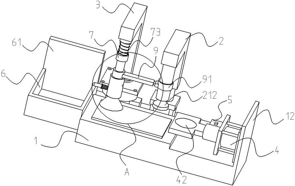
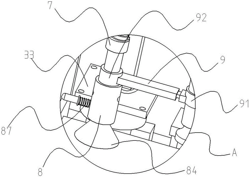
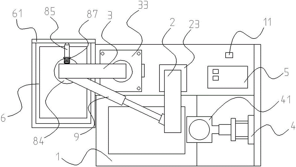
[0046] Such as Figure 1 to Figure 10 As shown, a fully automatic stamping machine includes a workbench 1, a power switch 11, a side plate 12, a lifting arm 2, a lifting rod 21, a positioning groove 211, a seal 212, a pressure sensor 22, a cylinder 23, and a rotary arm 3 , chute body 31, tension spring fixing frame 32, rotary motor 33, cylinder two 4, support body 41, ink pad tank 42, controller 5, storage tank 6, baffle plate 61, connecting body 7, sliding rod 71, pull Spring movable frame 72, extension spring 73, positioning rod 74, mounting body 8, mounting rod 81, piston body 82, track cavity 821, sliding wedge sliding hole 822, piston ball 823, fixed sleeve 83, inner vent hole 831, opening sucker 84. Suction cup opening and closing port 841, suction cup ventilation hole 842, contact pressure rod 85, ring protrusion 851, sliding wedge body 852, outer ventilation hole 86, spring two 87, spring one 88, fixed rod 89, t...

Embodiment 2

[0055] The following is a description of Embodiment 2.

[0056] In Embodiment 2, the same symbols are assigned to the same structures as in the above-mentioned embodiments, and the same descriptions are omitted. Embodiment 2 is improved on the basis of Embodiment 1, and the seal 212 of the device is detachably mounted on the lifting rod 21, and the seal 212 is an automatic ink-filling seal.

[0057] Beneficial effects of the embodiment

[0058] It can greatly improve the efficiency of stamping, and at the same time effectively reduce the labor repetition of adding ink pads and save costs.

[0059] When the device is in use, the workbench 1 is placed on a flat desktop, the document to be stamped is placed on the workbench 1, the power switch 11 is turned on, and the cylinder one 23 starts to lift under the control of the controller 5. Then drive the lifting arm 2 to reciprocate up and down, and then the lifting rod 21 reciprocates up and down, and the seal 212 realizes the st...


PUM


Abstract

The invention discloses a full-automatic seal stamping machine and belongs to the technical field of office equipment. The machine comprises a working table, a controller, a connector and a piston body, wherein an air cylinder 1 and a revolving motor are disposed in parallel along one rectangle edge on the working table; a lifting arm is disposed on the air cylinder 1; a lifting rod which faces downwards is firmly disposed under the lifting arm; a seal is firmly installed on the bottom of the lifting rod; a revolving arm is disposed on the revolving motor; an installation box is fixed under a positioning body; a slide-wedge slide hole is formed in the middle of the piston body; a piston ball is disposed on the lower part of the piston rod; the outer side of the piston body is sleeved by a fixation sleeve; and an opened suction disk is also fixed on the inner side of the fixation sleeve. According to the invention, the automation degree is high; practicability is high; the problem that efficiency of existing seal stamping work is low can be solved; a lot of time are saved in daily office work, and manpower labor is reduced; and the full-automatic seal stamping machine is highly practical.

Description

technical field [0001] The invention relates to the technical field of office equipment, in particular to a fully automatic stamp sealing machine. Background technique [0002] At present, in some electric power or bank statistics business, it often involves the operation of printing and stamping the bill. In the prior art, most of them still need the staff to manually stamp one by one, and then organize and store them. The operation steps are cumbersome. , The workload is too heavy, which is very inconvenient for the stamping personnel. [0003] An invention of patent number ZL201110371286.0, the application discloses a stamping machine, which includes a transmission mechanism and a stamping mechanism above the transmission mechanism, and completes the stamping operation under the instruction of the control device. The invention has a complex structure and needs manual picking and placing, which is inconvenient to use. [0004] Therefore we are in urgent need of a fully a...

Claims


Application Information

Patent Timeline
Patent Type & Authority Applications(China)
IPC IPC(8): B41K3/04B41K3/62B41K3/64
CPCB41K3/04B41K3/62B41K3/64
Inventor 郭映歧焦艳艳陶殿军潘磊周辉刘开颜
Owner JINAN CITY CHANGQING DISTRICT POWER SUPPLY CO OF STATE GRID SHANDONG ELECTRIC POWER CO
Why Eureka
Try Eureka