
Adhesive joint assembly integrated structure for antenna supporting truss and aluminum honeycomb plate

Antenna support and aluminum honeycomb technology, applied in the fuselage frame, transportation and packaging, aircraft parts, etc., can solve the problems of limited assembly accuracy, low utilization efficiency, and restrictions on the application and promotion of truss structures, so as to improve torsional stiffness and improve utilization efficiency effect

Active Publication Date: 2017-03-29
SHANGHAI SATELLITE ENG INST
View PDF5 Cites 13 Cited by
  • Summary
  • Abstract
  • Description
  • Claims
  • Application Information

AI Technical Summary

Problems solved by technology

[0003] 1) The truss structure is relatively simple, and the truss as a whole relies on space cable-stayed members to resist torsion, and the torsional stiffness of the truss is low;
[0004] 2) The utilization rate of the internal space of the truss is insufficient, and only the external plane of the truss can provide the installation load for the payload, and the utilization efficiency is low;
[0005] 3) The truss glued assembly method is simple and the assembly accuracy is limited, which can no longer meet the requirements of high-precision resolution satellites
[0006] The above deficiencies largely limit the application and popularization of truss structures in spacecraft structures.

Method used


Image

  • Adhesive joint assembly integrated structure for antenna supporting truss and aluminum honeycomb plate
  • Adhesive joint assembly integrated structure for antenna supporting truss and aluminum honeycomb plate
  • Adhesive joint assembly integrated structure for antenna supporting truss and aluminum honeycomb plate

Examples


Embodiment Construction

[0036] The present invention will be described in detail below in conjunction with specific embodiments. The following examples will help those skilled in the art to further understand the present invention, but do not limit the present invention in any form. It should be noted that for those of ordinary skill in the art, several changes and improvements can be made without departing from the concept of the present invention. These all belong to the protection scope of the present invention.

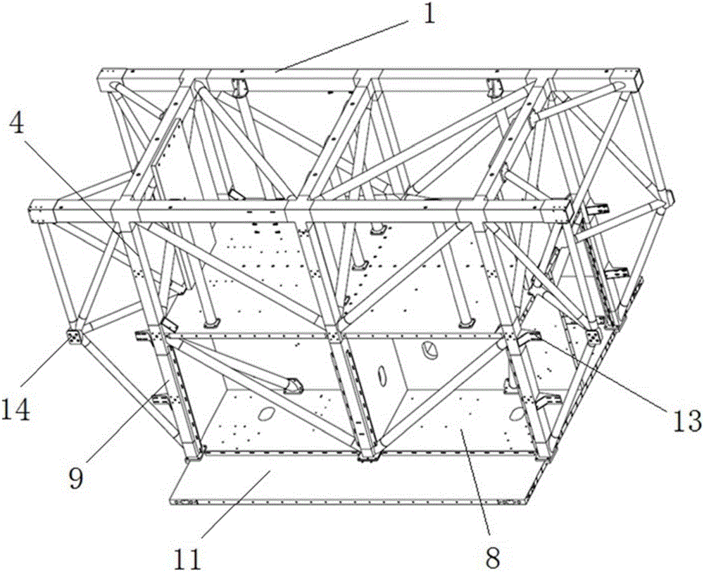
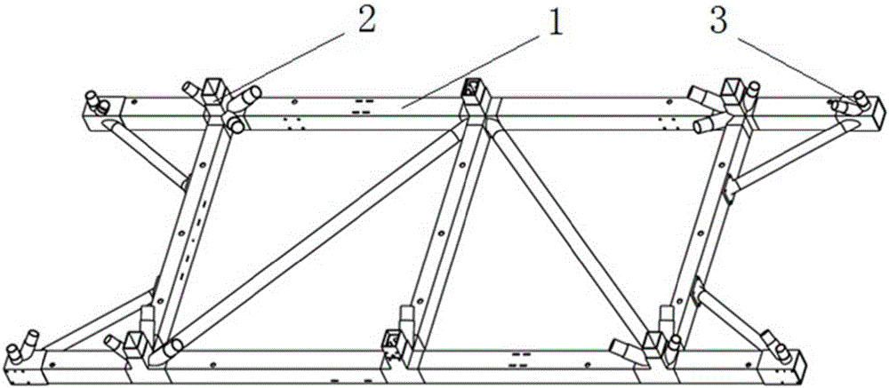
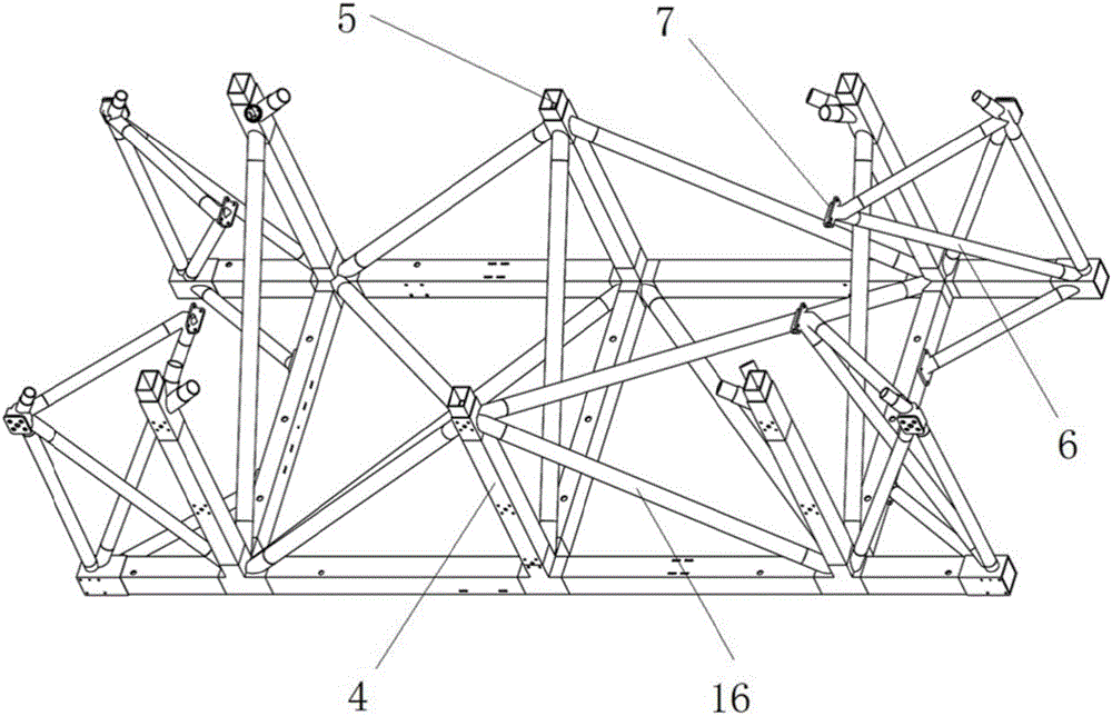
[0037] Such as figure 1 As shown, the present invention mainly includes: an antenna support truss (composed of a rod 1 and a support joint 2 and an installation joint 3 arranged on the rod 1), a support plate 8 (aluminum honeycomb panel is used in this embodiment), a stringer assembly (First beam 4 assembly and second beam 9 assembly), bottom plate 11 and corner box 13. The installation interface of the effective load is mainly composed of the supporting joint 2, the installation joint 3 ...


PUM


Abstract

The invention provides an adhesive joint assembly integrated structure for an antenna supporting truss and an aluminum honeycomb plate. The adhesive joint assembly integrated structure comprises a supporting truss, a first stringer assembly, a supporting rod, a supporting plate, a second stringer assembly and a bottom plate, wherein the supporting truss comprises a rod part as well as a supporting joint and a mounting joint arranged on the rod part; the first truss assembly comprises a plurality of first stringers, ends of the first stringers are connected with the supporting joint, and the other ends of the first stringers are equipped with stringer joints; one end of the supporting rod is connected with the mounting joint, and the supporting base is arranged at the other end of the supporting rod; the supporting plate is fixed with the mounting bases through the stringer joints; the second stringer assembly comprises a plurality of second stringers, ends of the second stringers are connected with the stringer joints, and the other ends of the second stringers are equipped with supporting bases; and the bottom plate is arranged on the supporting bases. The adhesive joint assembly integrated structure has the following innovative design: the carbon fiber antenna supporting truss and the aluminum honeycomb plate are integrally designed, and the honeycomb plate structure is introduced, so that torsion rigidity of the structural form of the truss honeycomb plate is greatly improved.

Description

Technical field [0001] The invention relates to an aerospace vehicle structure, in particular to an antenna support truss and aluminum honeycomb panel glued assembly integral structure capable of carrying a large number of payloads. Background technique [0002] At present, the carbon fiber truss structure in the spacecraft structure is simply composed of joints and rods, and the joints and rods are connected by bolts or glued. This kind of pure truss structure has the following shortcomings: [0003] 1) The truss structure is relatively simple, and the truss as a whole mostly relies on the space diagonal rods to resist torsion, and the torsional stiffness of the truss is low; [0004] 2) Insufficient utilization of the internal space of the truss, only the external plane of the truss can provide installation bearing for the effective load, and the utilization efficiency is low; [0005] 3) The truss gluing assembly method is simple and the assembly accuracy is limited, which can no ...

Claims


Application Information

Patent Timeline
IPC IPC(8): B64C1/36B64C1/06
CPCB64C1/064B64C1/065B64C1/36
Inventor 满孝颖王舒楠陈树海林德贵
Owner SHANGHAI SATELLITE ENG INST
Learn More