An integral compartment structure liquid propellant delivery device

A liquid propellant and delivery device technology, applied in aerospace vehicle propulsion system devices, transportation and packaging, fuel tanks of power devices, etc., can solve problems such as large mass and volume, restrictions, large system mass and space volume, etc., to achieve Realize the effect of gas-liquid isolation and prevent air entrainment

Active Publication Date: 2018-08-31
BEIJING LINJIN SPACE AIRCRAFT SYST ENG INST +1
View PDF5 Cites 0 Cited by
  • Summary
  • Abstract
  • Description
  • Claims
  • Application Information

AI Technical Summary

Problems solved by technology

[0003] The disadvantage of the existing integral compartment storage tank is that its working process requires the full participation of the control system. In order to realize the sequential delivery under various complex overloads, it is necessary to install sensors and control mechanisms in each compartment. The opening and closing of the propellant delivery pipelines of each compartment is controlled by the propellant consumption of the compartment, which leads to a relatively complicated work control process and internal structure of the tank, and the system mass and space volume are also relatively large
[0004] To sum up, the sequential delivery of integral compartment storage tanks can meet the requirements of propellant center of mass control and slosh suppression in complex flight trajectories, but the existing schemes and control systems are coupled with the working process, mass and volume, etc. its application

Method used


Image

  • An integral compartment structure liquid propellant delivery device
  • An integral compartment structure liquid propellant delivery device
  • An integral compartment structure liquid propellant delivery device

Examples


Embodiment Construction

[0023] Below in conjunction with accompanying drawing and specific embodiment the present invention is described in further detail:

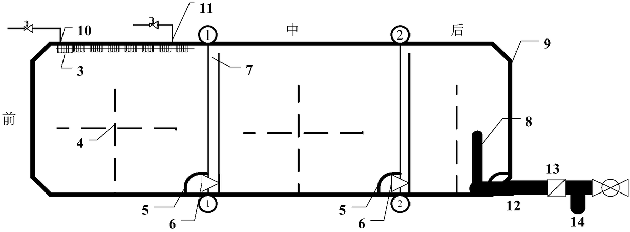
[0024] like figure 1 Shown is a schematic diagram of the overall structure of the liquid propellant delivery device in the empty oil state. It can be seen from the figure that a liquid propellant delivery device with an integral compartment structure includes a first partition 1, a second partition 2, and an energy-dissipating air guide groove 3. Anti-sway baffle 4, air bubble screen 5, baffle one-way valve 6, diversion channel 7, swing liquid collector 8, tank shell 9, pressurized air inlet 10, pressurized exhaust port 11 , Oil outlet pipeline 12; Wherein, storage tank shell 9 is the shell structure of liquid propellant conveying device; It is fixedly installed inside the storage tank shell 9; the energy dissipation air guide groove 3 is fixedly installed on the inner wall of the top of the storage tank shell 9; one end of the energy dissipati...


PUM


Abstract

The invention discloses an integral compartment structure liquid propellant conveying device, and relates to the field of pressurizing conveying systems. A storage box shell is a shell structure of the liquid propellant conveying device. A first partition plate and a second partition plate are fixedly installed in the storage box shell in the radial direction. A pressurizing air inlet and a pressurizing air outlet are formed in the two ends of an energy dissipation air guiding groove. An anti-swing baffle is fixedly arranged in an inner cavity of the storage box shell. Baffle one-way valves are fixedly arranged on the lower end side wall of the first partition plate and the lower end side wall of the second partition plate correspondingly. A flow guiding channel parallel to the first partition plate is arranged on one side of the first partition plate. A flow guiding channel parallel to the second partition plate is arranged on one side of the second partition plate. An oil outlet pipeline is fixedly arranged on the inner side wall of the lower end of the storage box shell and stretches out of the storage box shell. A swinging liquid collector is vertically and fixedly arranged at the end, located in the storage box shell, of the oil outlet pipeline. According to the integral compartment structure liquid propellant conveying device, the work process is simplified, a storage box is simple in structure, and the system mass and volume are reduced.

Description

technical field [0001] The invention relates to the field of pressurized delivery systems, in particular to a liquid propellant delivery device with an integral compartment structure. Background technique [0002] The existing integral compartment type storage tank is used in the aviation field. Its main technical content is to make full use of the internal space of the fuselage, and use the outer shell of the fuselage structure directly as the outer wall of the storage tank. The load-bearing structure or the wing is divided into a number of compartments that are independent in space and connected internally. Through the integral compartment structure storage tank, it can not only make full use of the internal structural volume of the fuselage to install more propellants, increase the range and endurance time, but also realize the sequential delivery of propellants and the overall center of mass control. [0003] The disadvantage of the existing integral compartment storage...

Claims


Application Information

Patent Timeline
Patent Type & Authority Patents(China)
IPC IPC(8): B64D37/08B64D37/32B64G1/40
CPCB64D37/08B64D37/32B64G1/402
Inventor 苏立超章成亮苏丙未石竟成谢雪明何春全刘建勇黄兴李王少慧
Owner BEIJING LINJIN SPACE AIRCRAFT SYST ENG INST
Why Eureka
Try Eureka