
Silencer pipe

一种消音、管道的技术,应用在声衰减领域,能够解决外壳沉重、难以制造成本等问题

Active Publication Date: 2021-11-26
GENERAL ELECTRIC TECH GMBH
View PDF0 Cites 0 Cited by
  • Summary
  • Abstract
  • Description
  • Claims
  • Application Information

AI Technical Summary

Problems solved by technology

For example, the enclosure is very heavy and also difficult and expensive to manufacture due to the cost of the material and the need for welding to form the panels

Method used


Image

  • Silencer pipe
  • Silencer pipe
  • Silencer pipe

Examples


Embodiment Construction

[0052] As described above, the present invention provides a sound dampening panel and sound dampening system comprising at least one plastic perforated side wall. In addition, the invention comprises acoustic panel sections or sections, (modular) acoustic panels and acoustic ducts which can slidably receive the acoustic panels.

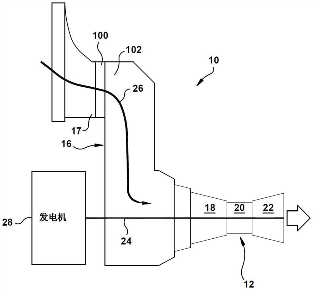
[0053] With reference to the accompanying drawings, figure 1 An exemplary industrial machine in the form of a turbine system 10 (eg, a single cycle gas turbine power generation system) in which a gas turbine system 12 may be included is depicted. Gas turbine system 12 may combust a liquid or gaseous fuel, such as natural gas and / or hydrogen-rich syngas, to generate hot combustion gases to drive gas turbine system 12 . Gas turbine system 12 includes an air intake section 16 , a compressor 18 , a combustor component 20 , and a turbine component 22 . Turbine member 22 is drivingly coupled to compressor 18 via shaft 24 . In operation, air (eg, ambient ...


PUM


Abstract

The present invention relates to a sound deadening panel section and related sound deadening ducts. The sound absorbing panel section may include sound absorbing material, a first shell surrounding the sound absorbing material, and a first coupler configured to couple the first shell to a second shell of an adjacent sound absorbing panel section. Acoustic panels may employ multiple sections that are joined together to form a single acoustic panel. The acoustic duct may include a frame forming a working fluid flow path and a plurality of acoustic panel mounts positioned within the frame, each configured to slidably receive an acoustic panel, such as those described herein.

Description

technical field [0001] The present invention relates generally to acoustic attenuation, and more particularly to silencer panels and related silencer ducts. Background technique [0002] Noise reduction systems are used on a large number of industrial machines, such as turbines, to reduce the acoustic impact on the surrounding area. In gas turbine systems, for example, noise reduction systems are applied in inlet ducts, gas turbine casings, and barrier walls. Traditionally, acoustic panels and acoustically treated walls have been employed in noisy areas in order to obtain the necessary acoustic reduction requirements. One mechanism to reduce acoustic impact is to treat the walls with sound absorbing material. Another mechanism is to place the sound-absorbing panel in the area where noise reduction is required, such as in the working fluid flow path in the intake system duct, to prevent noise leakage. [0003] With regard to sound deadening panels, each panel generally com...

Claims


Application Information

Patent Timeline
Patent Type & Authority Patents(China)
IPC IPC(8): F02C7/045
CPCF02C7/045F05D2260/96F05D2300/43G10K11/162F05D2260/36F05D2240/91F05D2230/51F05D2300/615F01D25/30F01N1/24
Inventor 张华L.默钱特J.I.穆罕默德V.I.彭亚文D.维努戈帕尔塞蒂
Owner GENERAL ELECTRIC TECH GMBH
Features
  • Generate Ideas
  • Intellectual Property
  • Life Sciences
  • Materials
  • Tech Scout
  • Unparalleled Data Quality
  • Higher Quality Content
  • 60% Fewer Hallucinations
Learn More