Bearing ball mounting device
A technology for installing devices and bearing balls, applied in bearing components, shafts and bearings, mechanical equipment, etc., can solve problems such as low work efficiency, high price, missing balls, etc., to avoid production efficiency decline, high work efficiency, and ingenious design. Effect
- Summary
- Abstract
- Description
- Claims
- Application Information
AI Technical Summary
Problems solved by technology
Method used
Image

Examples
Embodiment Construction
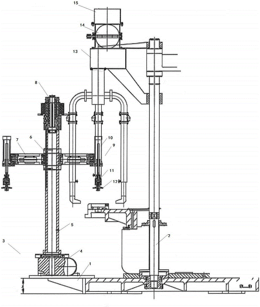
[0025] In order to make the technical means, creative features, goals and effects achieved by the present invention easy to understand, the present invention will be further elaborated below in conjunction with illustrations and specific embodiments.
[0026] Such as figure 1 As shown, a bearing ball installation device proposed by the present invention includes a base 1, a main control rod 2, an intermediate device 3, a rotating platform 4, a ball support 6 and a ball installation device 9,
[0027] The middle part of the base 1 is provided with an I-shaped groove, and both sides of the groove are provided with a circular through hole. The inside of the circular through hole is threaded, and the upper end of the groove is connected with a main control rod 2. Rod 2 is screwed to the groove by bolts;
[0028] The left side of the main control rod 2 is provided with an intermediate device 3, and the intermediate device 3 includes a rotating platform 4 arranged on the upper end ...
PUM
 Abstract
Description
Claims
Application Information
 - Generate Ideas
- Intellectual Property
- Life Sciences
- Materials
- Tech Scout
- Unparalleled Data Quality
- Higher Quality Content
- 60% Fewer Hallucinations
Browse by: Latest US Patents, China's latest patents, Technical Efficacy Thesaurus, Application Domain, Technology Topic, Popular Technical Reports.
© 2025 PatSnap. All rights reserved.Legal|Privacy policy|Modern Slavery Act Transparency Statement|Sitemap|About US| Contact US: help@patsnap.com