Substation safety lighting device based on fiber optic light technology

A technology for safe lighting and substations, applied in lighting devices, lighting device light guides, lighting device components, etc., to avoid potential safety hazards and ensure safe operation

Active Publication Date: 2019-02-15
PINGDINGSHAN POWER SUPPLY ELECTRIC POWER OF HENAN
View PDF7 Cites 0 Cited by
  • Summary
  • Abstract
  • Description
  • Claims
  • Application Information

AI Technical Summary

Problems solved by technology

[0011] In view of this, the purpose of the present invention is to address the deficiencies of the prior art and provide a substation safety lighting device based on fiber optic light technology, which not only solves the problem of substation lighting, but also can realize all-weather light extraction and ensure the safety of substation electricity use. while minimizing energy consumption

Method used


Image

  • Substation safety lighting device based on fiber optic light technology
  • Substation safety lighting device based on fiber optic light technology
  • Substation safety lighting device based on fiber optic light technology

Examples


Embodiment 1

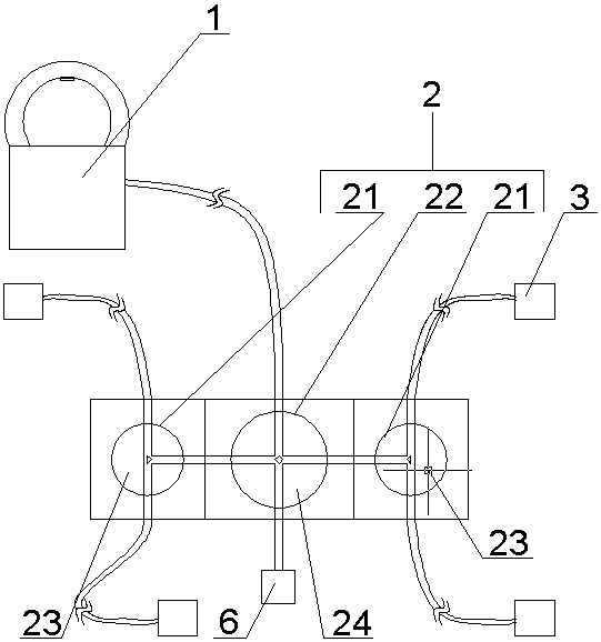
[0046] The substation safety lighting device based on optical fiber lamp technology includes a light-collecting mechanism 1, a converter 2 interconnected with the optical signal of the light-collecting mechanism 1, a control mechanism 4 interconnected with the optical signal of the converter 2, and the converter. 2 Light-emitting mechanisms 6 interconnected by optical signals, and radiation modules 3 interconnected by optical signals with the converter 2;

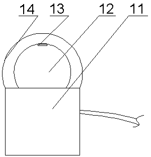
[0047] The light collecting mechanism 1 includes a base 11, an optical fiber arranged on the lower part of the base 11, a light collecting assembly 12 arranged on the upper part of the base 11, a photosensitive sensor 13 arranged on the upper part of the light collecting assembly 12, and a set The cover body 14 on the light concentrating assembly 12;

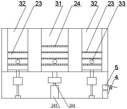
[0048] The converter 2 includes a housing, a conversion module arranged in the housing, an optical channel arranged between the conversion modules and in the housing, and a t...

Embodiment 2

[0058] The center of the housing is provided with a main vertical through hole 22, and the two sides of the housing are provided with auxiliary vertical through holes 21, and the main vertical through holes are provided with four optical passages at right angles to each other and on the same horizontal plane; The side walls of the secondary vertical through holes are provided with three T-shaped light channels.

[0059] The light-emitting mechanism 6 is an illuminating lamp interconnected with the converter 2 through optical signals.

Embodiment 3

[0061] The telescopic module is arranged on the electric telescopic rod 245 , and the telescopic module includes a stepping motor 244 and a main cylindrical base or an auxiliary cylindrical base arranged on the output shaft of the stepping motor 244 .


PUM


Abstract

The invention discloses a substation safety lighting device based on optical fiber lamp technology, which includes a light collecting mechanism, a converter interconnected with the optical signal of the light collecting mechanism, a control mechanism interconnected with the optical signal of the converter, and an optical signal interconnected with the converter. A light-emitting mechanism interconnected with signals, and a radiation module interconnected with the optical signal of the converter; the present invention collects sunlight through the light collector, then distributes the light through the conversion mechanism, and sets a light-emitting mechanism at the conversion mechanism to supplement light , to ensure that the light-consuming units can be illuminated when the sunlight is weak or at night, and to avoid potential safety hazards caused by the lighting circuit, it is worthy of application and promotion.

Description

technical field [0001] The invention relates to the technical field of power substation operation and maintenance equipment, in particular to a substation safety lighting device based on optical fiber lamp technology. Background technique [0002] The light guide lighting system (the standard name is the light guide daylight lighting system) is a new type of lighting device. The principle of the system is to efficiently collect natural light through the daylight cover and redistribute it into the system, and then transmit and strengthen it through a specially made light guide. The diffuser at the bottom of the system irradiates natural light evenly and efficiently to any place that needs light, and obtains special lighting effects brought by natural light. [0003] Compared with the traditional lighting system, the light guide lighting system has unique advantages, good development prospects and broad application fields. It is a truly energy-saving, environmentally friendly ...

Claims


Application Information

Patent Timeline
Patent Type & Authority Patents(China)
IPC IPC(8): F21S19/00F21S9/03F21V13/06F21V23/04
CPCF21S9/032F21S19/005F21V13/06F21V23/0464F21V2200/10
Inventor 智勇军武振宇李庆盈付晓司文跃陈瑾陆畅杨玉良张崔嵬智津津
Owner PINGDINGSHAN POWER SUPPLY ELECTRIC POWER OF HENAN
Why Eureka
Try Eureka