Eureka AIR delivers breakthrough ideas for toughest innovation challenges, trusted by R&D personnel around the world.

Cable partial discharge monitoring system

A partial discharge monitoring and partial discharge technology, applied in the cable field, can solve the problems of inability to accurately locate the cable discharge position and measure the discharge intensity, and achieve the effect of wide application range, high detection accuracy and reliable operation.

Inactive Publication Date: 2017-03-29
德阳瑞能电力科技有限公司
View PDF1 Cites 0 Cited by
  • Summary
  • Abstract
  • Description
  • Claims
  • Application Information

AI Technical Summary

Problems solved by technology

[0004] In order to solve the problem that the prior art cannot accurately locate the discharge position and measure the discharge intensity of the cable in the running state, the present invention provides a cable partial discharge monitoring system capable of accurately locating the discharge position of the cable in the running state and measuring the discharge intensity , the cable partial discharge monitoring system is suitable for monitoring overhead cables between substations and users

Method used


Image

  • Cable partial discharge monitoring system
  • Cable partial discharge monitoring system

Examples


Embodiment 1

[0030] The cable partial discharge monitoring system of this embodiment includes the Internet, five partial discharge detectors, two community cable management stations, two mobile terminals and a control center;

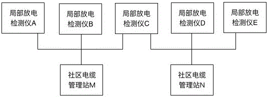
[0031] like figure 1 As shown, the partial discharge detector A1, partial discharge detector B2, partial discharge detector C3, partial discharge detector D4, and partial discharge detector E5 are respectively installed on the five utility poles;

[0032] like figure 2 As shown, community cable management station M manages partial discharge detector A1 and partial discharge detector B2, community cable management station N manages partial discharge detector D4 and partial discharge detector E5, community cable management station M and community cable management Station N jointly manages the partial discharge detector C3 at the junction of the community;

[0033] The partial discharge detector includes a detection module and a communication module, the detection m...

Embodiment 2

[0065] This embodiment is further optimized on the basis of Embodiment 1. The partial discharge detector further includes a self-inspection module. The self-inspection module verifies the partial discharge detector, and the communication module sends the verification result to the control center.

[0066] The partial discharge detector ensures its reliable operation through self-inspection, which can effectively avoid the phenomenon of missing or wrong signals due to the failure of the partial discharge detector.

Embodiment 3

[0068] This embodiment is further optimized on the basis of Embodiment 2. The mobile terminal further includes an alarm module, and the alarm module sends out an alarm bell when the receiving module receives task assignment information.

[0069] The alarm bell can attract the attention of maintenance personnel and remind them to accept maintenance tasks in time.


PUM


Abstract

The invention provides a cable partial discharge monitoring system. The system comprises a network, at least one partial discharge detector, a control center, at least one community cable management station and at least one mobile terminal, wherein the partial discharge detector and the control center are connected through the network, the community cable management station and the control center are connected through the network, and the mobile terminal and the community cable management station are connected through the network. The system is advantaged in that the discharge position of a cable in an operation state can be accurately positioned, discharge intensity is measured, and the system is suitable for monitoring an overhead cable between a transformer station and a user.

Description

technical field [0001] The invention relates to the field of cables, in particular to a cable partial discharge monitoring system. Background technique [0002] During the operation of the cable, the aging of the cable insulation will lead to the occurrence of partial discharge. The change of the partial discharge indicates that there is a defect in the cable insulation that may endanger the safe operation of the cable. Safety incidents may occur. [0003] The Chinese invention patent application with the filing date of March 2, 2012 and the application number of 201210075267.8 discloses a cable partial discharge detection system, including a partial discharge tester, a photoelectric converter, a signal processor, and a display terminal. The signal processors are respectively It is connected with a photoelectric converter and a display terminal, the photoelectric converter is connected with a partial discharge tester, and the partial discharge tester is connected with a cab...

Claims


Application Information

Patent Timeline
Patent Type & Authority Applications(China)
IPC IPC(8): G01R31/12
CPCG01R31/1272
Inventor 李杰陆晓阳
Owner 德阳瑞能电力科技有限公司
Why Eureka
Eureka Blog
Learn More