Exposure apparatus

The technology of an exposure device and an adjustment device is applied in the field of integrated circuit equipment manufacturing, which can solve the problems of surface error and deformation of the substrate surface, and achieve the effect of realizing the adjustment of high-order wave aberration.

Active Publication Date: 2017-03-29
SHANGHAI MICRO ELECTRONICS EQUIP (GRP) CO LTD
View PDF8 Cites 0 Cited by
  • Summary
  • Abstract
  • Description
  • Claims
  • Application Information

AI Technical Summary

Problems solved by technology

At the same time, due to the deformation of the larger mask due to gravity, the surface of the substrate will also have surface errors.

Method used


Image

  • Exposure apparatus
  • Exposure apparatus
  • Exposure apparatus

Examples


Embodiment Construction

[0023] Specific embodiments of the present invention will be described in detail below with reference to the drawings.

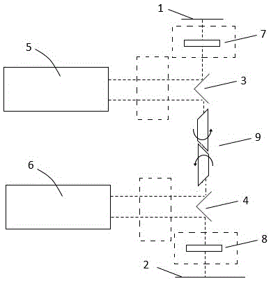
[0024] figure 1 It is a schematic diagram of the structure of the exposure device of the present invention. Such as figure 1 As shown, the exposure device sequentially includes an object plane 1, a focal plane adjustment device 7, a plane mirror group 3, a Dyson optical system 5, a prism group 9 composed of two Dove prisms, a plane mirror group 4, and a Dyson type optical system. Optical system 6, magnification adjustment device 8, image plane 2, and field diaphragm (not shown).

[0025] The dotted box shown in the figure is the possible placement position of the electroactive lens or the liquid lens, but it is not limited to the position shown in the figure. The electroactive lens or the liquid lens can also be placed in all optical paths that may adjust the image field.

[0026] The plane mirror group 3, the plane mirror group 4, the focal plane adjustment devic...


PUM


Abstract

The invention discloses an exposure apparatus. The exposure apparatus comprises an object plane, a focal plane adjustment apparatus, a plane reflector group, a first Dyson type optical system, a prism group which consists of two Dove prisms, a plane reflector group, a second Dyson type optical system, a rate adjustment apparatus and an image plane on a light path along a light beam propagation direction; and the exposure apparatus also comprises an image field adjustment mechanism in the light path. Compared with the prior art, rotation of the image field is realized by the Dove prisms; a right-angle reflector is replaced by two single-sheet reflectors, so that the inclination and the focal plane of the image plane can be adjusted respectively; and in addition, a plurality of electroactive lens or liquid lens driven by electrodes are arranged in the light path, so that more-complex plane type changes of the lens, and high-order wave aberration adjustment of image quality can be realized.

Description

Technical field [0001] The invention relates to the field of integrated circuit equipment manufacturing, in particular to an exposure device. Background technique [0002] The flat panel display technology is developing rapidly and the size is getting bigger and bigger. If an objective lens with a larger field of view is used for exposure, the yield can be effectively improved. However, with the increase of the field of view of the objective optical system, the difficulty in design and manufacturing will increase. Use the same objective lens with a moderate field of view size to splice multiple fields of view into the required large field of view in a certain arrangement, and select the number of splicing according to the required field of view size. This not only achieves the requirement of a large field of view, but also reduces the difficulty of optical processing and manufacturing, and has high compatibility and flexibility. [0003] Since multiple sub-objectives are used fo...

Claims


Application Information

Patent Timeline
Patent Type & Authority Applications(China)
IPC IPC(8): G03F7/20G02B17/08
Inventor 孙晶露何经雷
Owner SHANGHAI MICRO ELECTRONICS EQUIP (GRP) CO LTD
Why Eureka
Try Eureka