Waveform continuous transformation method for reducing switching frequency

A technology of switching times and waveforms, which is used in output power conversion devices, AC power input is converted into AC power output, electrical components, etc., to reduce switching losses, reduce output harmonics, and reduce switching times.

Inactive Publication Date: 2017-03-29
BEIJING INSTITUTE OF GRAPHIC COMMUNICATION
View PDF5 Cites 3 Cited by
  • Summary
  • Abstract
  • Description
  • Claims
  • Application Information

AI Technical Summary

Problems solved by technology

[0012] Although the waveform continuous conversion technology mentioned in the above-mentioned patent documents can reduce the switching times by up to 1/3, it only has this effect at some op

Method used


Image

  • Waveform continuous transformation method for reducing switching frequency
  • Waveform continuous transformation method for reducing switching frequency
  • Waveform continuous transformation method for reducing switching frequency

Examples


Embodiment Construction

[0044] In order to make the objectives, technical solutions, and advantages of the present invention clearer, the following further describes the present invention in detail in conjunction with specific embodiments and with reference to the accompanying drawings.

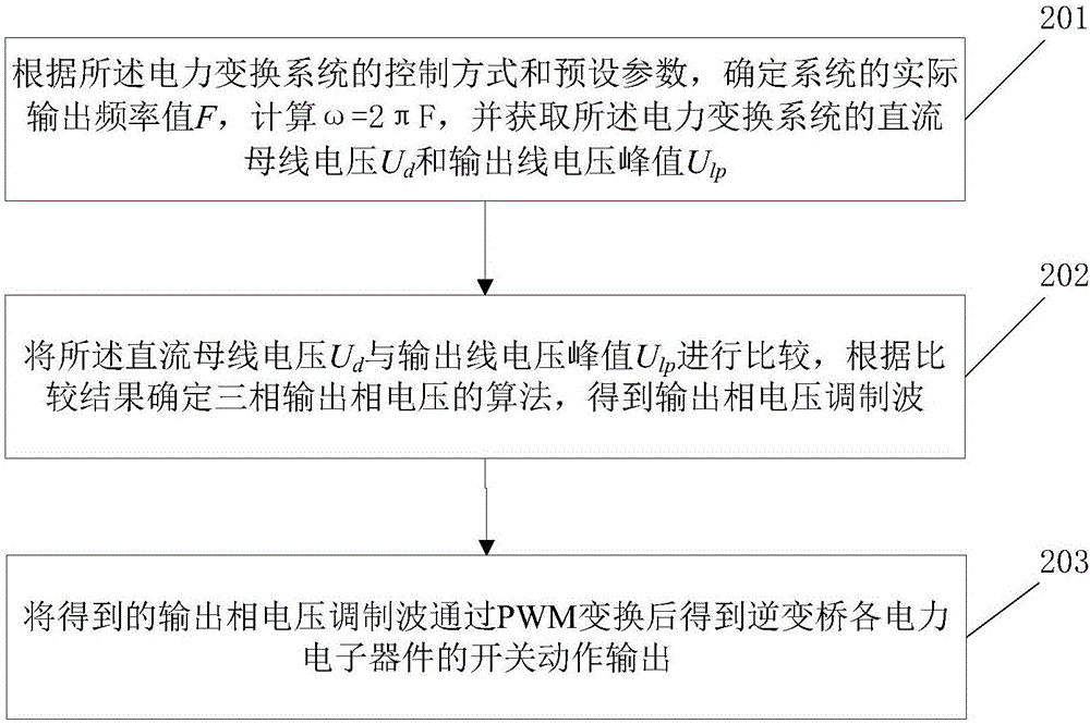
[0045] The embodiment of the present invention provides a waveform continuous conversion method that reduces the number of switching times. reference figure 2 , Is a flowchart of a waveform continuous conversion method for reducing switching times according to an embodiment of the present invention.

[0046] The waveform continuous conversion method for reducing switching times includes the following steps:

[0047] Step 201: Determine the actual output frequency value F of the system according to the control mode and preset parameters of the power conversion system, calculate ω=2πF, and obtain the DC bus voltage U of the power conversion system d And output line voltage peak U lp .

[0048] In this embodiment, using imag...


PUM


Abstract

The invention discloses a waveform continuous transformation method for reducing switching frequency. The method is applied to a power transform system, and comprises the following steps: according to a control mode and preset parameters of the power transform system, determining an actual output frequency value F of the system, calculating omega=2 [pi]F, and obtaining a DC bus voltage Ud and an output line voltage peak Ulp of the power transform system; comparing the DC bus voltage Ud and the output line voltage peak Ulp, determining three-phase output phase voltage algorithms according to the comparison results, and obtaining output phase voltage modulation wave; and carrying out PWM conversion on the obtained output phase voltage modulation wave to obtain switch action output of each power electronic device of an inverter bridge. The method can reduce switching frequency of each power electronic device by 1/3 under the condition of keeping inverter bridge output line voltage be a sine wave, thereby greatly reducing switching loss without causing distortion of the output line voltage, and reducing output harmonic wave.

Description

Technical field [0001] The present invention relates to the technical field of power conversion, in particular to a waveform continuous conversion method that reduces the number of switching times. Background technique [0002] As the switching speed of power electronic devices increases, the switching frequency of inverters is getting higher and higher. Therefore, the switching loss of power electronic devices becomes the main factor in the power loss of inverters. The higher the switching frequency, the more switching times. The greater the switching loss. Reducing the switching times of power electronic devices can directly reduce the switching losses of power electronic devices, and at the same time reduce the probability of damage caused by excessive temperature of the device due to the heat dissipated by the loss. More importantly, it can improve the working efficiency of the inverter. Further improve the reliability of the system. [0003] The switching times of power elec...

Claims


Application Information

Patent Timeline
IPC IPC(8): H02M5/458H02M1/12
CPCH02M1/12H02M5/458
Inventor 张皓陈天牧续明进卻银槐田景洋
Owner BEIJING INSTITUTE OF GRAPHIC COMMUNICATION
Why Eureka
Try Eureka