Boxing sandbag with improved structure

A boxing and sandbag technology, applied in the field of fitness equipment, can solve the problems of high manufacturing cost, cumbersome installation, and high transportation cost, and achieve the effects of improving safety in use, saving transportation costs, and reducing production costs

Inactive Publication Date: 2017-04-05
苏州大角体育用品有限公司
View PDF5 Cites 4 Cited by
  • Summary
  • Abstract
  • Description
  • Claims
  • Application Information

AI Technical Summary

Problems solved by technology

The disadvantage of this technical solution is: the pile body is a filled solid pile body, the weight is heavy and cannot be adjusted, and the transportation cost is high, which relatively increases the purchase cost of equipment and cannot meet the needs of consumers.
Although this technical solution solves some of the above-mentioned problems, it still has the following deficiencies: First, the base of the pile body adopts a fixed base, and the base is directly connected with the pile body. damage; Secondly, the structure is more complicated, the installation is cumbersome, and the manufacturing cost is high

Method used


Image

  • Boxing sandbag with improved structure
  • Boxing sandbag with improved structure
  • Boxing sandbag with improved structure

Examples


Embodiment 1

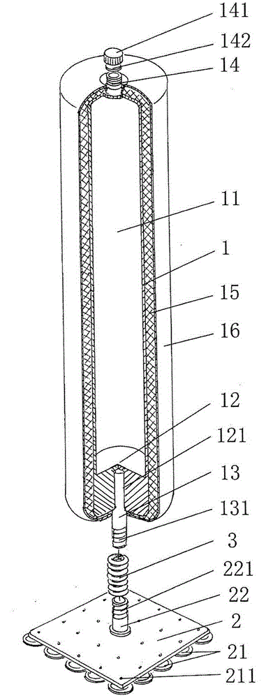
[0021] see figure 1 , figure 2 , the present invention relates to a boxing sandbag with improved structure, comprising a cylinder 1, a base 2 and a spring 3, the cylinder 1 is connected to the base 2 through the spring 3, and the characteristics are: the cylinder 1 There is a medium cavity 11 inside, and an upper column fixing seat 12 is formed at the bottom of the column cylinder 1 in the height direction. An upper column insertion cavity 121 is opened at the center of the upper column fixing seat 12. The opening of the upper column insertion cavity 121 faces Next, one end of an upper column 13 is embedded in the upper column insertion cavity 121, and the other end of the upper column 13 extends downward and protrudes from the lower bottom surface of the column tube 1, and at the same time forms a There is an upper spiral groove 131, and a medium inlet and outlet 14 protrudes from the center of the top of the cylinder 1 in the height direction. The medium inlet and outlet 1...

Embodiment 2

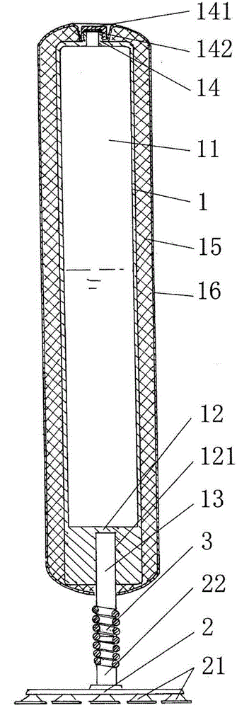
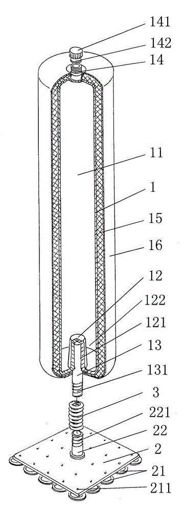
[0027] see figure 1 , figure 2 and combine image 3 , the structure of the second embodiment is basically the same as that of the first embodiment, the difference is that: the bottom of the cylinder 1 in the height direction is recessed into the medium chamber 11 with an upper column fixing seat 12, and the center of the upper column fixing seat 12 is There is an upper column insertion cavity 121, and there is a certain space between the upper column fixing seat 12 and the wall of the column tube 1 and forms a circle of medium relief groove 122, which communicates with the medium chamber 11, so that The medium relief groove 122 reduces the production cost of the column 1 and further reduces the weight of the column 1, which is more conducive to reducing the transportation cost.

Embodiment 3

[0029] see figure 1 , figure 2 and combine Figure 4 The structure of the third embodiment is basically the same as that of the first embodiment, except that the lower end of the lower column 22 is fixedly connected with the connection plate 23, and the connection plate 23 is installed on the connection seat 24 through the connection plate fixing screw 231, And this connection base 24 is fixed on the pile base 25 by the connection base fixing screw 241 again, and described pile base 25 is comparatively heavy and difficult to overturn, has good grip performance, has improved the stability of boxing sandbag.

[0030] see figure 1 , figure 2 , image 3 and combine Figure 4 , describe the use method of the present invention: when in the transportation state, there is no medium in the medium chamber 11, the weight of the sandbag is reduced to the minimum, which can effectively reduce the transportation cost; and when it is put into use, the column cylinder 1, Base 2 and sp...


PUM


Abstract

A boxing sandbag with an improved structure belongs to the technical field of body-building equipment and comprises a cylinder, a pedestal and a spring. The cylinder is connected with the pedestal via the spring. The cylinder is characterized by containing a medium cavity; an upper stand column fixing seat is formed on the bottom in a cylinder height direction; an upper stand column insertion cavity is formed in the upper stand column fixing seat; an opening of the upper stand column insertion cavity faces down; one end of an upper stand column is fixedly embedded into the upper stand column insertion cavity; the other end of the upper stand column downwardly extends and extends out of the lower base surface of the cylinder; the end part of the other end is provided with an upper spiral groove; a medium inlet/outlet is protruded from the center of the top in the cylinder height direction; the medium inlet/outlet is communicated with the medium cavity; the medium inlet/outlet is provided with a cylinder cover connected with the same; and a sealing seat is cushioned between the cylinder cover and the medium inlet/outlet. Transporting cost can be saved; damage to wrist joints can be avoided; safe use can be achieved; and the boxing sandbag with the improved structure has great overall strength, simple structure and requires low production cost and is suitable for large-scale batch production.

Description

technical field [0001] The invention belongs to the technical field of fitness equipment, and in particular relates to a boxing sandbag with improved structure. Background technique [0002] Nowadays, people's lives are becoming more and more comfortable, but the number of people suffering from diseases due to lack of exercise is increasing year by year. Therefore, when people gradually begin to realize the importance of exercise and fitness, various fitness clubs have sprung up like mushrooms after rain. Boxing As a piece of conventional sports equipment, sandbags are in increasing demand. At present, there are various types of boxing sandbags on the market, and the more common boxing sandbags mainly include the ceiling type and the pile type. Both of them generally have the problems of non-adjustable weight, heavy weight and high transportation costs. [0003] In the prior art, such as the "wooden pile sandbag" provided by the Chinese invention patent application publicat...

Claims


Application Information

Patent Timeline
Patent Type & Authority Applications(China)
IPC IPC(8): A63B69/22
Inventor 顾星
Owner 苏州大角体育用品有限公司
Why Eureka
Try Eureka