Device for rotary cutting of blocky dry ice

A rotary cutting device and dry ice technology, which is applied in metal processing and other directions, can solve the problems of unable to carry out regular rotary cutting, pollute dry ice, and difficult to maintain the shape, etc., and achieve the effect of simple and controllable path, uniform transportation, and compact device

Inactive Publication Date: 2017-04-05
XIAMEN JINRUIYI IND & TRADING CO LTD
View PDF8 Cites 2 Cited by
  • Summary
  • Abstract
  • Description
  • Claims
  • Application Information

AI Technical Summary

Problems solved by technology

The falling area of ​​the dry ice of this mechanism is in the same area as the rotary drive device of the rotary cutting plate. The rotary drive device needs to be cleaned, otherwise it will contaminate the dry ice; moreover, the dry ice has a complicated route and sublimates during the process.
When the dry ice block is rotary cut to the end, its shape is difficult to maintain, and regular rotary cutting cannot be performed, and the other side of the rotary cutting plate cannot enter the dry ice collection area from the cut, so a piece of dry ice must always be left as a waste

Method used


Image

  • Device for rotary cutting of blocky dry ice
  • Device for rotary cutting of blocky dry ice
  • Device for rotary cutting of blocky dry ice

Examples


Embodiment 1

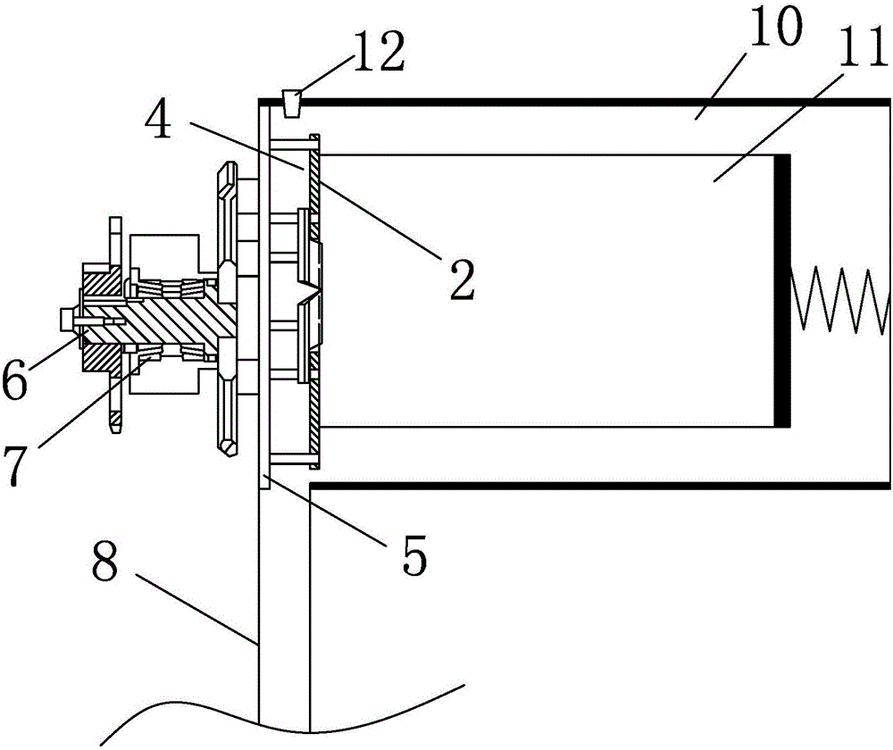
[0019] like figure 1 As shown, the block dry ice rotary cutting device of the present embodiment includes: a container (10), used to place dry ice (11), the first side of the container is provided with a pressing device (12), which pushes the dry ice to the second side, the second side is provided with a rotary cutting plate as a rotary cutting side plate, which is a side plate of the container, and the side plate includes a rotatable rotary cutting plate (5), such as figure 2 , image 3 As shown, it is generally circular, and it is fixed with a blade (4), a support plate (2), the blade (4) and the support plate (2) are generally on the same plane, and the sharp end of the blade (4) protrudes outward. Support plate (2), can stretch out 0.5-2 millimeter, or carry out proper adjustment according to the loose degree of dry ice. Between the rotary cutting board (2) and the blade (4) and the supporting board (3), there is a retaining column (9), whose function is to leave a cer...

Embodiment 2

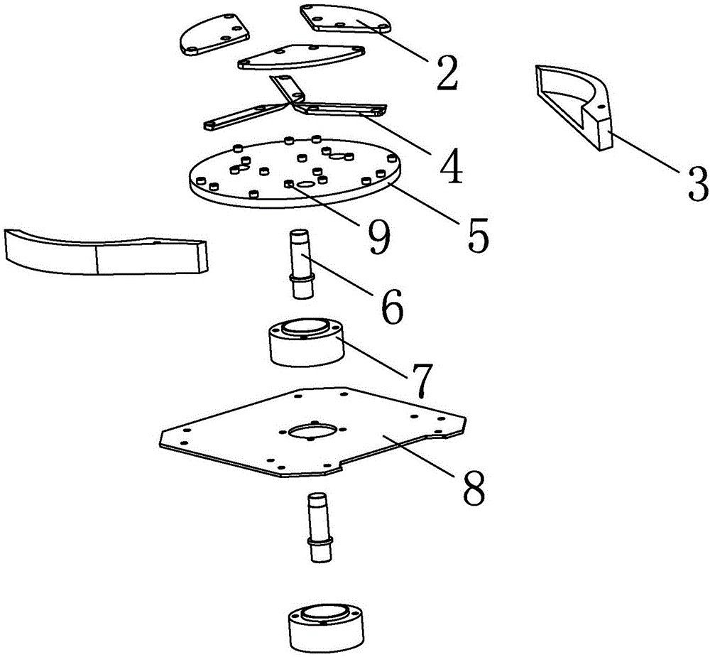
[0020] Embodiment 2: as Figure 4 , 5 , shown in 6, it is different from embodiment 1 in that the support plate is canceled, and the blade is changed to a scraper, and the scraper is as Figure 7 As shown, it includes a plane (2.1), an opening (2.2), and a blade (2.3), the scraper (2) is fixed on the rotary cutting board (5), and there is a post between the scraper (2) and the rotary cutting board ( 9), the scraper rotates with the rotary cutting plate (5), and the blade (2.3) protrudes out of the plane (2.1), and the dry ice is rotary-cut and dropped from the opening (2.2).


PUM


Abstract

The device for rotary cutting of blocky dry ice comprises a container used for containing the dry ice. A pressing device is arranged on the first side of the container and pushes the dry ice to the second side. A rotary cutting plate is arranged on the second side face. Blades and a supporting block are fixed to the rotary cutting plate. The blades incline in the direction from the second side to the first side and exceed the supporting block. A clearance is reserved among the supporting block, the blades and the rotary cutting plate. An opening is formed in the corresponding position, below the clearance, of the bottom face of the container, and rotary-cut dry ice particles drop down from the opening. According to the device, a dry ice dispersion device is arranged in the container for completion, a transmission device is arranged outside the container, the dry ice is not contaminated, little dry ice sublimates in the dispersion process, and the device is more compact.

Description

technical field [0001] The invention relates to a device for grinding block dry ice into particles suitable for blasting medium blasting. Background technique [0002] Dry ice has the property of sublimation, and is used in fields such as grinding and deburring of precision injection parts, and cleaning of electronic components. The finished product of dry ice is generally in the form of a block. It is necessary to grind the block of carbon dioxide into small particles, and then use the injection device to spray the carbon dioxide particles through the accelerator pump and toward the workpiece. In U.S. Patent Application Publication No. 2003 / 0064665A1, a dry ice rotary cutting device is disclosed, such as Image 6 As shown, the dry ice cubes are closely attached to the rotary cutting board, and one side of the rotary cutting board 54 is provided with a blade. The dry ice enters the other side of the rotary cutting plate from the opening of the rotary cutting plate, falls in...

Claims


Application Information

Patent Timeline
Patent Type & Authority Applications(China)
IPC IPC(8): B26D1/29B26D7/02
CPCB26D1/29B26D7/02
Inventor 林欲晓
Owner XIAMEN JINRUIYI IND & TRADING CO LTD
Why Eureka
Try Eureka