Axis vent pipe structure of turbine engine and turbine engine

A technology for turbine engines and ventilation pipes, applied to engine components, machines/engines, mechanical equipment, etc., can solve the problems of increasing engine lubricating oil consumption, increasing engine lubricating oil system maintenance costs, etc.

Active Publication Date: 2017-04-05
AECC COMML AIRCRAFT ENGINE CO LTD
View PDF6 Cites 0 Cited by
  • Summary
  • Abstract
  • Description
  • Claims
  • Application Information

AI Technical Summary

Problems solved by technology

This will increase the oil consumption of the engine and increase the maintenance cost of the engine oil system

Method used


Image

  • Axis vent pipe structure of turbine engine and turbine engine
  • Axis vent pipe structure of turbine engine and turbine engine
  • Axis vent pipe structure of turbine engine and turbine engine

Examples


no. 1 example

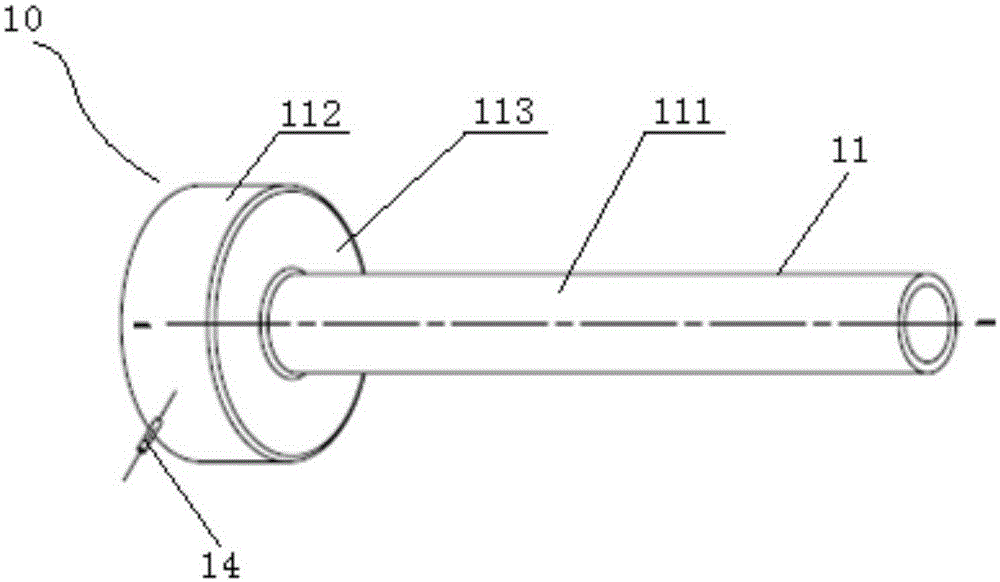
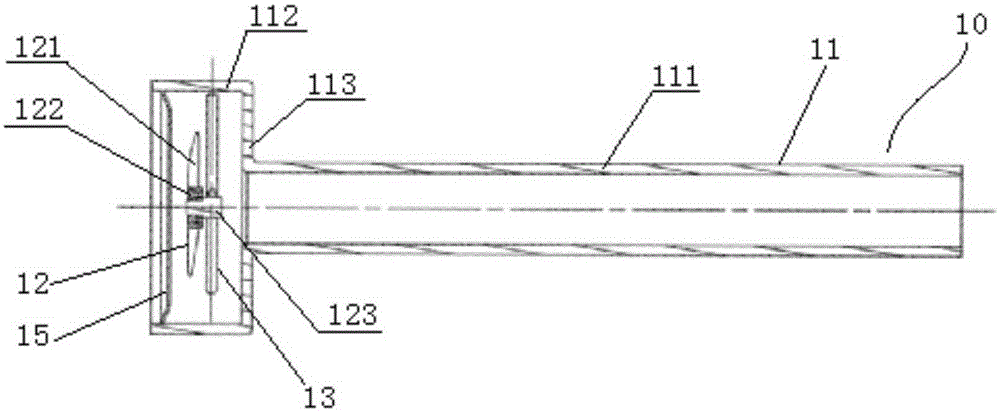
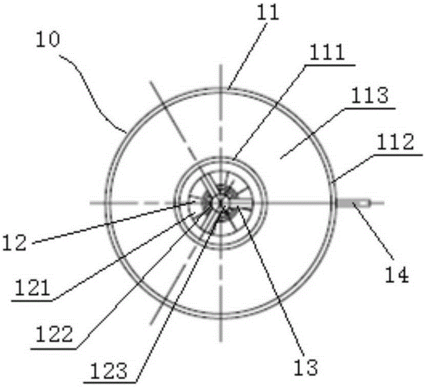
[0043] Figure 1 to Figure 4 Shown is the axial vent pipe structure of the turbine engine according to the first embodiment of the present invention. like Figure 1 to Figure 4 As shown, the axial ventilation pipe structure 10 of the first embodiment includes an axial ventilation pipe 11 , a wind wheel assembly 12 , a support frame 13 , an oil outlet structure and a front hollow baffle 15 . The oil outlet structure includes an oil outlet and an oil outlet pipe 14 .

[0044] like Figure 1 to Figure 2 As shown, the axial ventilation pipe 11 includes a main pipe section 111 , a wind wheel assembly installation pipe section 112 and a rear hollow baffle 113 . The diameter of the wind wheel assembly installation pipe section 111 is larger than the main pipe section 112 . The wind wheel assembly installation pipe section 111 and the main pipe section 112 are arranged coaxially. The wind wheel assembly installation pipe section 111 is arranged on the front side of the main pipe ...

no. 2 example

[0056] Figure 5 to Figure 8 Shown is the axial vent pipe structure of the turbine engine according to the second embodiment of the present invention. like Figure 5 to Figure 8 As shown, the axial ventilation pipe structure 20 of the second embodiment includes an axial ventilation pipe 21 , a wind wheel assembly 22 , a support frame 23 and an oil outlet structure. The oil outlet structure includes an oil outlet and an oil outlet pipe 24 .

[0057] like Figure 5 and Image 6 As shown, in the second embodiment, the axial ventilation pipe 21 includes a main pipe section 211 , a wind wheel assembly installation pipe section 212 and a rear hollow baffle 213 .

[0058] like Image 6 and Figure 7 As shown, in the second embodiment, the wind wheel assembly 22 includes an impeller 221 , a bearing 222 and a wheel shaft 223 . The wind wheel assembly 22 is arranged in the wind wheel assembly installation pipe section 212 through the support frame 23 , wherein the support frame 2...


PUM


Abstract

The invention discloses an axis vent pipe structure of a turbine engine and the turbine engine. The axis vent pipe structure comprises an axis vent pipe, a wind wheel assembly and an oil outlet structure, the axis vent pipe comprises a main pipe section, a wind wheel assembly installation pipe section and a back hollow baffle with a first through hole, the wind wheel assembly installation pipe section is arranged on the front side of the main pipe section in the axial direction of the axis vent pipe, the back hollow baffle is located between the wind wheel assembly installation pipe section and the main pipe section, and the wind wheel assembly installation pipe section and the main pipe section are communicated through the first through hole; the wind wheel assembly comprises an impeller which is arranged in the wind wheel assembly installation pipe section and can conduct centrifugal separation on oil drops in oil-gas mixing air flow entering the axis vent pipe, and the back hollow baffle prevents the oil drops obtained through centrifugal separation from entering the main pipe section; and the oil outlet structure comprises an oil outlet for guiding the oil drops obtained through centrifugal separation out of the axis vent pipe. According to the technical scheme, the lubricating oil consumption amount of the turbine engine can be reduced, and the maintaining cost can be reduced.

Description

technical field [0001] The invention relates to the field of engines, in particular to an axial ventilation pipe structure of a turbine engine and the turbine engine. Background technique [0002] The lubricating oil system of a turbine engine used as an aeroengine is mainly used to lubricate and cool the bearings of the engine. During normal operation of the engine, the sealing air used to seal the bearing cavity flows from the bearing cavity to the shaft vent tube. In the prior art, the sealing air flowing out from the bearing cavity is usually an oil-air mixed flow containing a part of lubricating oil droplets. When the engine is running, the lubricating oil droplets are discharged out of the shaft center ventilation pipe together with the oil-air mixed flow. This will increase the oil consumption of the engine and increase the maintenance cost of the engine oil system. Contents of the invention [0003] The purpose of the present invention is to provide a kind of sha...

Claims


Application Information

Patent Timeline
Patent Type & Authority Applications(China)
IPC IPC(8): F01D25/18
Inventor 邵兴晨陈辉煌李松阳
Owner AECC COMML AIRCRAFT ENGINE CO LTD
Why Eureka
Try Eureka