Continuous variable valve lift system control method and system and vehicle

A valve lift and control method technology, applied in engine control, output power, machine/engine, etc., can solve problems such as affecting valve lift, single lift mode, and valve lift consistency, and achieve consistency. , to avoid the effect of machining tolerances

Active Publication Date: 2017-04-05
GREAT WALL MOTOR CO LTD
View PDF12 Cites 5 Cited by
  • Summary
  • Abstract
  • Description
  • Claims
  • Application Information

AI Technical Summary

Problems solved by technology

[0005] However, the variable valve lift mechanical mechanism is complex, and the clearance between the various kinematic pairs in the variable valve lift system, as well as the various parts in the system will deform to varying degrees under different loads of the engine. Both will affect the valve lift, so that the valve lift of each cylinder will be different
[0006] In addition, the traditional non-continuously variabl

Method used


Image

  • Continuous variable valve lift system control method and system and vehicle
  • Continuous variable valve lift system control method and system and vehicle
  • Continuous variable valve lift system control method and system and vehicle

Examples


Embodiment Construction

[0033] It should be noted that, in the case of no conflict, the embodiments of the present invention and the features in the embodiments can be combined with each other.

[0034] The present invention will be described in detail below with reference to the accompanying drawings and examples.

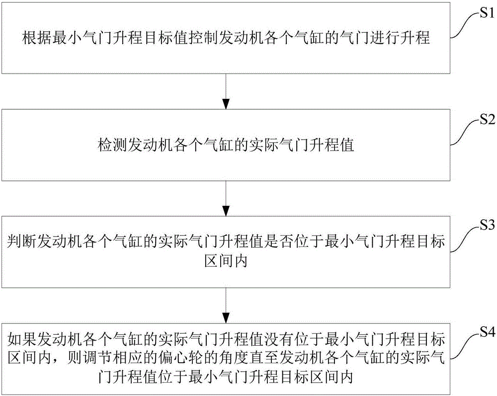
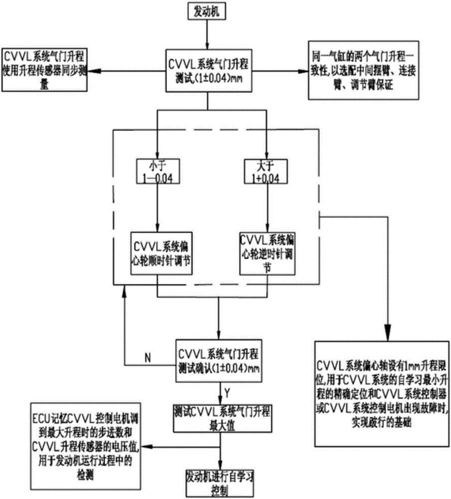
[0035] figure 1 It is an overall flow chart of the control method of the continuously variable valve lift system according to an embodiment of the present invention. figure 2 It is a detailed flowchart of a control method of a continuously variable valve lift system according to an embodiment of the present invention.

[0036] Such as figure 1 shown, combined with figure 2 , a control method for a continuously variable valve lift system according to an embodiment of the present invention, comprising the following steps:

[0037] S1: Control the lift of the valves of each cylinder of the engine according to the minimum valve lift target value.

[0038]S2: Detect the actual valve li...


PUM


Abstract

The invention provides a continuous variable valve lift system control method and system and a vehicle. The method includes the following steps that S1, valve lifts of all air cylinders of an engine are controlled according to a minimum valve lift target value; S2, actual valve lift values of all air cylinders of the engine are detected; S3, whether the actual valve lift values of all air cylinders of the engine are within the minimum valve lift target interval or not is judged; and S4, if the actual valve lift values of all air cylinders of the engine are not within the minimum valve lift target interval, the angles of corresponding eccentric gears are adjusted until the actual valve lift values of all air cylinders of the engine are within the minimum valve lift target interval. By means of the method, consistency of the valve lifts of all air cylinders of an internal combustion engine can be guaranteed, and influences of machining tolerance of parts in the system, the fit clearance of the parts and deformation of the parts on the valve lifts are avoided.

Description

technical field [0001] The invention relates to the technical field of automobiles, in particular to a control method, system and vehicle of a continuously variable valve lift system. Background technique [0002] Energy and environmental issues are the most severe challenges faced by human beings in the 21st century. As the power machinery with the highest thermal efficiency and the most widely used at present, the internal combustion engine generates 90% of the total power of power plants used in the world. It is the world's petroleum energy. main consumption channel. With the increase of car ownership, the oil consumption of internal combustion engines will increase rapidly, and the contradiction between oil supply and demand will inevitably become increasingly serious. While consuming a large amount of energy, internal combustion engines are also the biggest source of pollution to the atmospheric environment, especially the urban atmospheric environment. This shows that ...

Claims


Application Information

Patent Timeline
IPC IPC(8): F02D13/02
CPCY02T10/12
Inventor 刘涛张文龙徐黎明胡佳佳尹吉李冠宇刘胜强房艳龙张华
Owner GREAT WALL MOTOR CO LTD
Why Eureka
Try Eureka