
Cutting guide plate top mechanism

A positioning plate and cross-shaped technology, applied in welding equipment, laser welding equipment, metal processing equipment, etc., can solve the problems of unstable positioning and low production efficiency, and achieve the effect of convenient operation, simple structure and stable positioning state

Inactive Publication Date: 2017-04-12
宋琳
View PDF0 Cites 0 Cited by
  • Summary
  • Abstract
  • Description
  • Claims
  • Application Information

AI Technical Summary

Problems solved by technology

[0003] In order to solve the problems of unstable positioning and low production efficiency in the top of the laser cutting positioning plate, the present invention provides a cross positioning plate structure

Method used


Image

  • Cutting guide plate top mechanism
  • Cutting guide plate top mechanism

Examples


Embodiment Construction

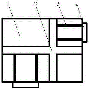
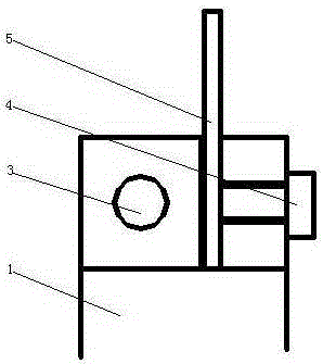
[0010] As shown in the figure, there is a cross-shaped notch 2 on the top of the positioning plate 1 where the positioning position is required, and threaded holes 3 are added in the front, rear, left and right directions.

[0011] During work, if it is necessary to increase the auxiliary pattern plate 5 in the front and rear directions, the auxiliary pattern plate 5 is put into the horizontal notch 2 and fixed with screws 4; Put it into the longitudinal notch 2 and fix it with screw 4.


PUM


Abstract

A cutting guide plate top mechanism is provided; the features are that a to-be-positioned position on the top of a guide plate is provided with a cross-notch; in addition, screw holes are added in front, back, left and right directions at the same time; a conventional laser cutting guide plate top mechanism is unstable in positioning, and low in production efficiency; the cutting guide plate top mechanism can solve said problems, and is the ideal design for laser cutting guide plate top.

Description

technical field [0001] The invention relates to the field of automobile molds, in particular to a positioning plate top mechanism suitable for laser cutting. Background technique [0002] At present, the product parts after the drawing of the car first need to be laser cut the outline and holes for the car manufacturer to carry out pre-loading and debugging. The product parts are small in batches. In the laser cutting process, the simple method is usually to use plasticine and single-sided positioning boards. After positioning the product and then cutting the parts, the positioning of the plasticine is unstable, and the quality of the produced workpiece is poor or even scrapped; the single-sided positioning plate can only be positioned on one side. In order to ensure the stability of positioning, only increase the number of positioning plates. Contents of the invention [0003] The invention provides a cross positioning plate structure to solve the problems of unstable pos...

Claims


Application Information

Patent Timeline
Patent Type & Authority Applications(China)
IPC IPC(8): B23K26/38B23K26/70
CPCB23K26/38
Inventor 宋琳
Owner 宋琳
Learn More