Supercharge Your Innovation With Domain-Expert AI Agents!

High-pressure continuous production waste oil filter device with automatic slag scraping and slag discharge

A high-pressure, oil filtration technology, applied in filtration and separation, fixed filter element filters, separation methods, etc., can solve the problems of filter screen, filter cloth damage, filter screen, filter cloth clogging, time-consuming and other problems, to improve production efficiency , The effect of good filtration quality and reliable performance

Active Publication Date: 2018-12-28
XINJIANG FUKE OIL PROD CO LTD
View PDF6 Cites 0 Cited by
  • Summary
  • Abstract
  • Description
  • Claims
  • Application Information

AI Technical Summary

Problems solved by technology

[0002] Because waste oil contains a lot of dregs, natural sedimentation and centrifugal separation are often used for filtration, but for dregs with a density close to the density of waste oil, filter screens and filter cloth filters can only be used to filter, because the filtration pressure is limited to Within 0.6MPa, there are also certain shortcomings;
[0003] 1. After a certain period of work, the meshes of the filter screen and filter cloth are clogged, and the filter cloth of the filter screen must be cleaned of dregs, and the filter machine needs to be disassembled to replace the filter cloth, which directly affects the normal production
[0004] 2. Cleaning the filter screen and filter cloth is time-consuming and laborious, and it is easy to cause damage to the filter screen and filter cloth;
[0005] 3. Because the filtration pressure is limited within 0.6MPa, the filtration effect cannot be achieved for waste oil with high viscosity

Method used


Image

  • High-pressure continuous production waste oil filter device with automatic slag scraping and slag discharge
  • High-pressure continuous production waste oil filter device with automatic slag scraping and slag discharge

Examples


Embodiment Construction

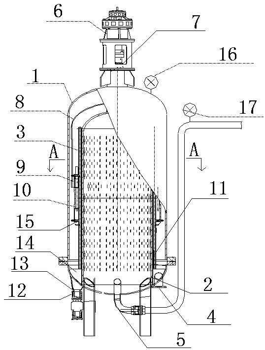
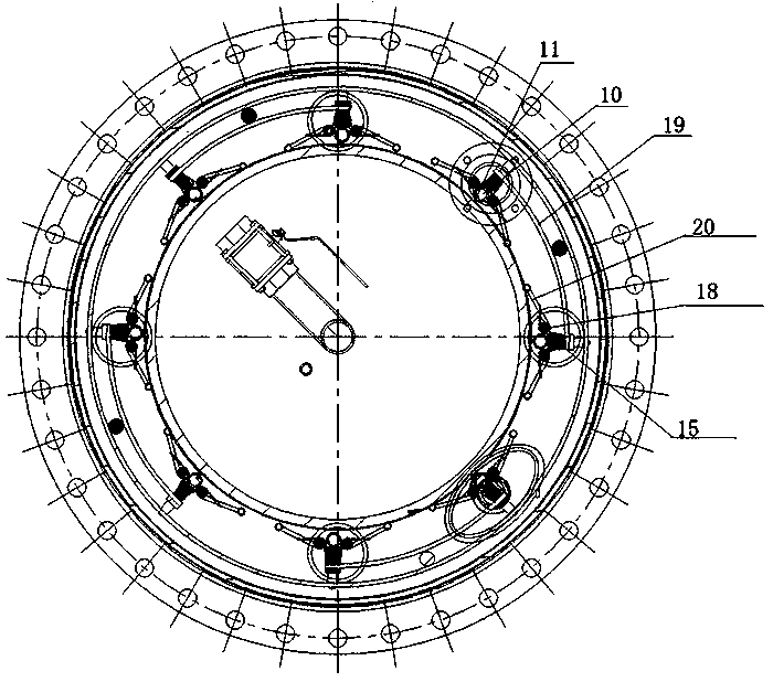
[0011] A high-pressure continuous production waste oil filtering device with automatic slag scraping and slag discharge, such as figure 1 , figure 2 Shown, in vertical tank body 1, be provided with the liner 2 of evenly distributed through hole, the opening of liner bottom is connected with the bottom surface of tank body 1, and filter screen 3 is set on the outer wall of liner 2, will The tank body 1 is divided into an oil inlet chamber and a filter chamber, an oil inlet pipe 4 is arranged on the bottom surface of the oil inlet chamber of the tank body 1, an oil outlet pipe 5 is arranged on the bottom surface of the tank body 1 of the filter chamber, and an oil outlet pipe 5 is arranged on the upper end of the tank body 1 A vertical shaft driven by a motor, a reducer 6 and a ratchet mechanism 7 is provided, and the vertical shaft located in the tank body 1 is connected to the rotating half-tank 8 provided on the upper part of the oil inlet chamber of the tank body, and the l...


PUM


Abstract

The utility model discloses an automatic sediment of scraping of high pressure continuous production, arrange the waste oil filter equipment of sediment, set up the inner bag of through -hole in vertical tank, the inner bag is connected with a jar body, set up the filter screen on the outer wall of inner bag, cut apart into oil feed chamber and filter chamber with the jar body, physically set up oil pipe in the oil feed chamber at the jar, set up oil pipe on the jar body of filter chamber, it passes through the motor to set up in the upper end of the jar body, the vertical scroll that reduction gear and ratchet drove, it rotatory half jar to be located a jar internal vertical shaft connection, at rotatory half jar sub -unit connection and scrape the knife rest, the scraper at the scraper shelf location, the scraper cooperatees with the filter screen, set up row's sediment motorised valve on the oil feed chamber jar body, the top of the jar body with go out oil pipe on is installing respectively and is connecing electric manometer. The utility model discloses it is rational in infrastructure, the dependable performance, the waste oil filtering quality who carries high pressure is good, dregs on can the automatic clear filter screen, the automatic clear dregs can automatic continuous production, can improve production efficiency greatly.

Description

technical field [0001] The invention belongs to a waste oil filter device for high-pressure continuous production, and is a production device for physically purifying waste oil, in particular to a waste oil filter device for automatic slag scraping and slag discharge in high-pressure continuous production. Background technique [0002] Because waste oil contains a lot of dregs, natural sedimentation and centrifugal separation are often used for filtration, but for dregs with a density close to the density of waste oil, filter screens and filter cloth filters can only be used to filter, because the filtration pressure is limited to Within 0.6MPa, there are also certain shortcomings; [0003] 1. After a certain period of work, the meshes of the filter screen and filter cloth are clogged, and the filter cloth of the filter screen must be cleaned of dregs, and the filter machine needs to be disassembled to replace the filter cloth, which directly affects the normal production. ...

Claims


Application Information

Patent Timeline
Patent Type & Authority Patents(China)
IPC IPC(8): B01D29/33B01D29/64
CPCB01D29/33B01D29/6476
Inventor 涂晶涂莹涂登源
Owner XINJIANG FUKE OIL PROD CO LTD
Features
  • R&D
  • Intellectual Property
  • Life Sciences
  • Materials
  • Tech Scout
  • Unparalleled Data Quality
  • Higher Quality Content
  • 60% Fewer Hallucinations
Learn More